VM Tubes: 3 - Klystrons
VM Tubes: 3 - Klystrons

Velocity Modulated Tubes: The Klystron
Following the work of Oskar Heil and his wife, the principle of velocity-variation tubes was also approached for other microwave amplifying tubes. The final application for the tube known as klystron is usually accredited in the early 1939 to Hahn and Metcalf and to Russell and Sigurd Varian, two brothers that worked for a while at the Stanford Physics Department with Professor Bill Hansen. Hansen had developed the resonant cavity, named ‘rumbatron’, and its related theory, essential for the klystron structure. Sperry Gyroscope Company had been attracted by the work for a blind-landing system and financed its initial development.
Of course other people worldwide were investigating similar devices more or less in the same days. Among them we should remember:
- Geiger M. who wrote articles on VM tubes around 1939 (Telefunken Röhre No. 16, page 177)
- Jobst G., on the VM tubes as oscillators, Telefunken Hansmitteillungen, Vol. 20, 1939
- Recknagel A. and Nesslinger, in Jahrbuch A.E.G. Forsch., Vol. 6, Feb. 1939
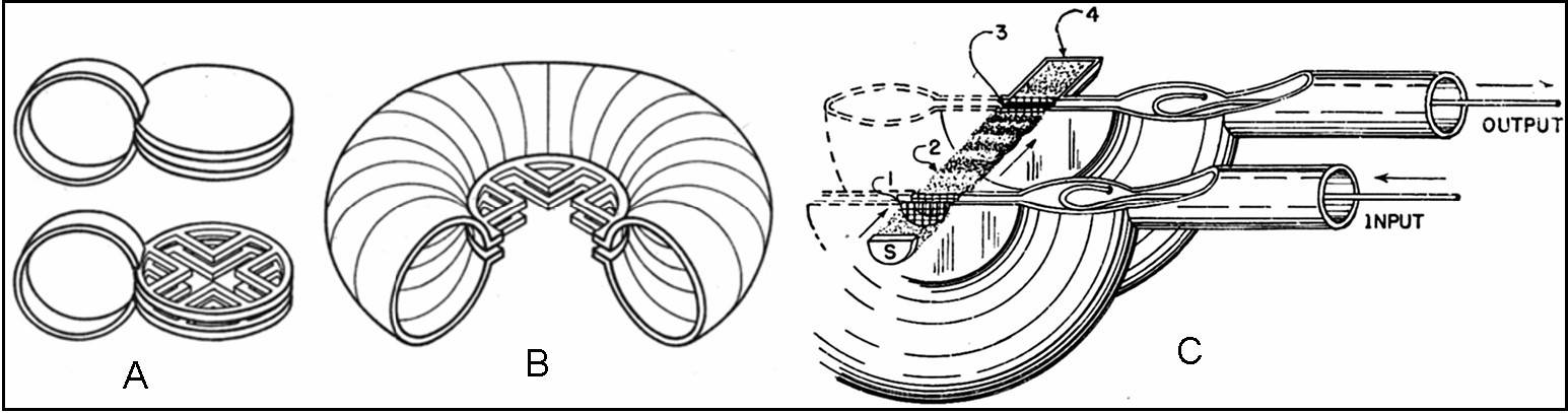
Fig. 1 – A and B show how the single turn LC resonator evolved in the ‘rumbatron’. The cavity may be considered as the result of many elementary sections, each being similar to A, all parallel connected. This connection results in very low inductance value. The shape of the capacitor in the middle of the cavity easily interacts with an electron beam. Q of this kind of resonator is very high. The early form of klystron amplifier is represented in C. Here the stream of electrons coming out from the source S crosses the short gap (1) of the first resonator. When passing through the gap, also referred to as buncher, electrons are subjected to acceleration depending upon the instantaneous value of the electric field between the capacitive rings. As result of the impressed acceleration, some electrons speed-up while other slow-down, to form bunches of electrons in the drift space (2) where no external field is impressed. The electron beam, whose density is now modulated by the input signal, crosses the second gap (3), also known as catcher, delivering energy to the cavity and to output. Electrons are then captured by the collector (4).
----------------------------------------------------------------------------------------------
The linear beam klystron
Two forms of such a device, also called ‘linear beam klystron’, are given in the following figure.
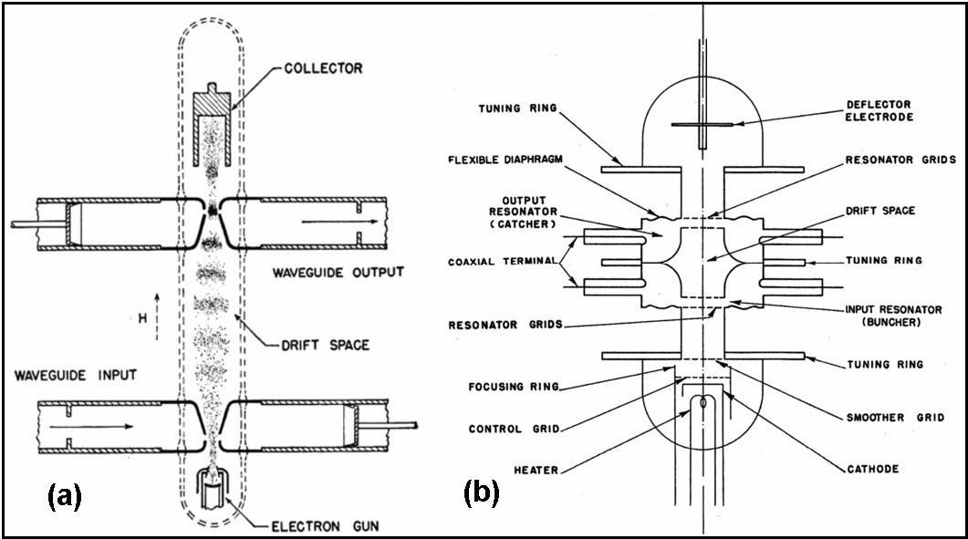
Fig. 2 – Left, draft of a linear beam klystron with external resonating cavities, in this case part of input and output waveguides. Right, in this Sperry design the resonating cavities are embedded in the tube itself and flexible diaphragms allow some tuning.
In fig. 2(a) the tube has four metal rings, the solid black sections, that form the capacitive gaps inside the glass body and connect to the waveguide resonating chambers outside. In the second example, the body of the klystron, from the upper to the lower tuning rings, is all metal with two flexible diaphragms to tune the two internal cavities. Domed glass seals support the electron gun, cathode and focusing grids, and the collector, here referred to as deflector. In both cases geometry and operating conditions are selected to have optimum bunching just at the catcher gap.
The electron gun is usually of convergent type, to have enough current density in the beam. The most common type is the ‘Pierce gun’, from the name of its designer, J. R. Pierce of Bell Telephone. Because of the repelling forces existing in dense electron beams, high power klystrons usually require some beam focusing system. The ion-focused beam is commonly used in klystrons for TV repeaters: here a small flux of positive ions counteracts the repelling forces, being captured by a ion trap before they could strike on the cathode surface. Also electrostatic or magnetic focusing are widely used. To improve efficiency, since interactions with gaps take place in the outer zone of the beam, Sperry devised a cathode capable of generating a hollow-beam.
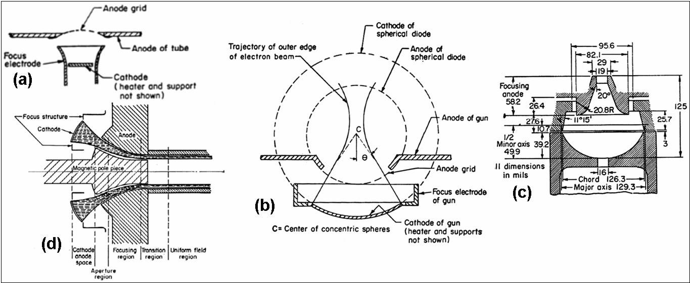
Fig. 3 – 3(a) shows the empirically designed gun used in the 2K25. 3(b) shows the Pierce gun, part of a spherical diode with a focusing electrode, while in 3(c) is given the section of a gun devised by O. Heil at Bell System. 3(d) shows a Sperry gun for generating hollow beams.
In a linear klystron the second cavity, corresponding to the catcher, may be tuned at a given harmonic frequency of the input signal and in this case the tube operates as frequency multiplier. Of course the catcher gap also remodulates crossing electrons in time-quadrature with respect to the residual modulation. In dual gap structures, as those of fig. 2, electrons are captured by the collector and no use is made of the secondary modulation. But cascaded structures can be built at no extra cost along the same beam when higher gain is required: here additional gaps take advantage of the secondary modulation. Cascaded klystron tubes are in common use as output amplifiers in high power transmitters, as TV repeaters, fed by relatively low power frequency multiplier and driver stages. In the following picture there are some of early external cavity klystron tubes developed by Bell Labs. also including cascade types. In these tubes details of the internal electrode structure are well visible.

Fig. 4 – Linear beam klystron tubes developed by Bell Laboratories. 4(a), 4(b) and 4(c) are very early prototypes developed prior to WWII. 4(b), 4(f) and 4(g) are cascade types.

Fig. 5 - This image shows two integral cavity linear klystrons, the second one being a frequency multiplier with coaxial input on the lower large resonating cavity and waveguide output.
Linear beam klystron tubes are not suitable for amplification of low level signals but have found relevant applications in high-power CW amplifiers, as television repeaters or CW radar equipment.
-----------------------------------------------------------------------------------------------
Reflex klystrons
Any linear beam klystron may operate as oscillator adding a feedback connection between output and input cavities. But when a klystron must just be operated as oscillator its structure may be simplified, leaving only one gap and negatively biasing the electrode that before was the collector. In this type of tube, referred to as reflex klystron, the negative electrode is called repeller. Electrons that have already crossed the gap, being consequently bunched, are forced by repeller to cross back the same gap that now performs the function of catcher. The principle of a reflex klystron structure is given below.
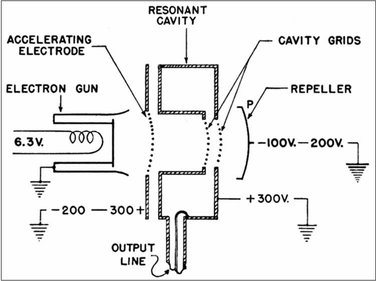
Fig. 6 – Draft of a reflex klystron structure, showing the repeller electrode and the single cavity with gap acting as buncher for electrons coming from the electron gun and as catcher for electrons pushed back by the repeller. Bunching occurs along the way from the cavity to the vicinity of the repeller and back.
As for linear beam devices, also reflex klystrons were built in a variety of types. Many came with integral or factory installed resonator, while other were designed for mounting into external resonating cavities, supplied by the manufacturer of the equipment. Reflex klystrons of the first type were available over an extremely extended range of frequencies, usually for small and medium output power, and have been widely used as local oscillator in microwave receivers or even in communication relay equipment. Klystrons using external cavities were used in microwave instrumentation and generators. In this case the range was usually determined by the resonating frequency limits of piston-tuned cavities and the frequency coverage could be in the order of 2:1 or even higher.
-----------------------------------------------------------------------------------------------
Picture gallery of some reflex klystrons
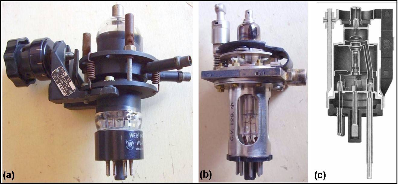
Fig 7 - Some of the early reflex klystron designs in common production during WWII. From left the 417, S-band integral cavity model designed by Sperry; the WL-417 of the picture, yet coming with a model 12 Sperry tuner, was manufactured by Westinghouse. 7(b) shows a British CV129 with external factory-installed tunable cavity. Even if this solution granted fixed geometry of the gap, it was quite complex. 7(c) shows a section of 2K25 (RMA code for the Western Electric design 723A/B), the most popular X-band reflex klystron. In its sturdy all-metal body output signal is fed to the external cavity through the coaxial probe protruding from the quasi-octal base.
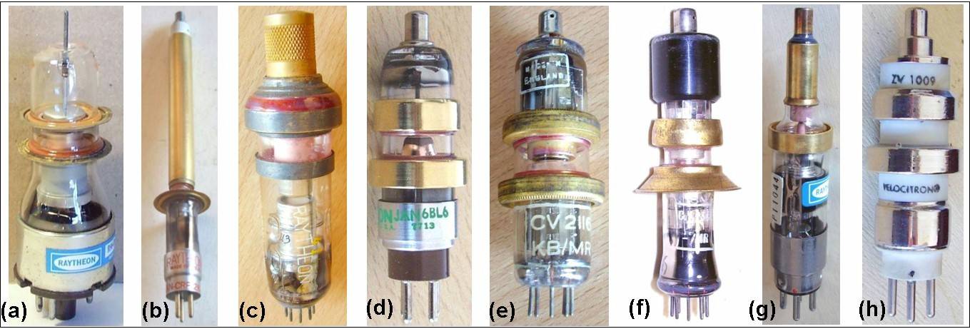
Fig. 8 – Shapes of some external cavity reflex klystrons. Rings that connect the internal gap to the external cavity have shapes designed to exactly fit in different cavities, yet allowing easy pull-out of the tubes for service. 8(a) 2K28 delivers 125 mW from 1200 to 3750 MHz. 8(b) 2K48 operates from 4 to 11GHz. 8(c) 5777 covers from 0.6 to 2.4 GHz. 8(d) 6BL6 covers from 1.4 to 6.5 GHz. 8(e) CV2116 is a British klystron that tunes from 1.8 to 4.5 GHz. 8(f) Also CV2346 is a British design operating from 8 to 10 GHz. 8(g) QKK1315, used in the HP 620B EHF generator, tunes from 7 to 11 GHz. 8(h) This ceramic-metal body ZV1009 ‘Velocitron’ from Polarad tunes from 1500 to 6000 MHz.
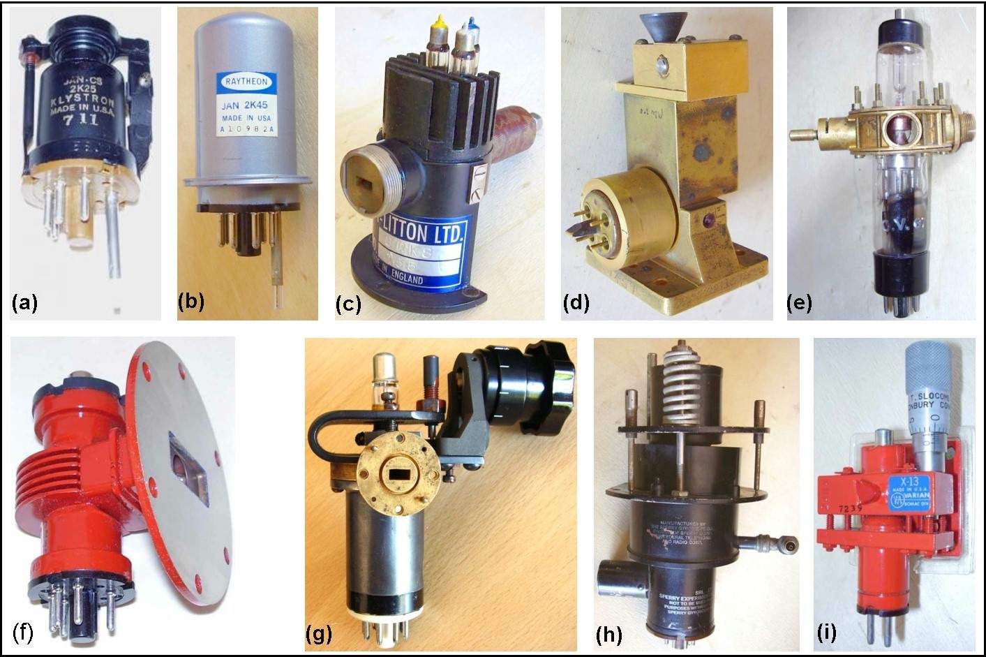
Fig. 9 – Overview of integral cavity reflex klystrons. 9(a) 2K25 (WE 723A/B) was the most popular X-band klystron, mechanically tunable from 8.5 to 9.7 GHz. 9(b) 2K45 operated over the same range of 2K25, with electronic tuning based upon bimetal struts heated by a tuning diode. 9(c) 8RK8 from Elliot-Litton Ltd. tunes over the Ka band. 9(d) This Western Electric 459A was used in microwave relays. 9(e) CV67 was one of the earliest British designs by EMI. Its factory-installed resonator was quite heavy and complex. 9(f) VA220 family includes power devices intended for microwave relay applications. 9(g) This Raytheon QK290 tunes from 29.70 to 33.52 GHz. 9(h) SRL-17 is a power klystron from Sperry tuning from 750 to 990 MHz and delivering 1.8W output power. 9(i) X-13 from Varian was intended as a precision source tunable from 8.2 to 12.4 GHz.
-------------------------------------------------------------------------------------------------
High-power klystrons
Since 1939 John Woodyard at Stanford University had built a two-cavity oscillator delivering 250 watts continuous at 750 MHz. Around 1940 high-power klystron solutions for radar transmitters were investigated by M. L. Oliphant at the Birmingham University, until the multicavity magnetron by Randall and Boot started to operate. In 1943 the TPS-7 CW radar used a three-cavity two kilowatts output klystron. In 1947 high voltage power structures were investigated by Ginzton and the Varian brothers at Stanford University.
In 1951 Varian introduced the first high-power klystron amplifier for UHF television transmitters. This tube described in Electronics, October 1951 issue, may be considered the forerunner of the many power amplifiers developed both in US and in Europe for television service. Starting from General Electric specifications for a power amplifier capable being driven by conventional 50W units based upon planar triodes, Varian designed an innovative cascaded klystron family. Tubes were capable of delivering over than 5 KW at any frequency between 500 and 1200 MHz, depending upon the staggered-tuned resonating cavities, with power gain of 250 and bandwidth of 5.6 MHz at 1-dB. By design a 24 inches beam of about 2 amperes was required to pass through the 1 inch inside diameter resonators, with 10KV collector voltage. A special cathode was designed to grant long and stable operative life. The emitting surface was a piece of 0.1 inch thick tantalum foil. It was heated by back electron bombardment from an auxiliary tungsten filamentary cathode behind the emitting surface. Differently from oxide coated types, the life of such a cathode even under severe operating conditions was only limited by the life of the tungsten heater. Its emission was stable and free from poisoning problems. Varian granted 10,000 hours continuous operation and claimed the easy replacement of the entire cathode assembly after this period. External focusing coils prevented beam spreading in its way through the resonators. The collector was water-cooled.
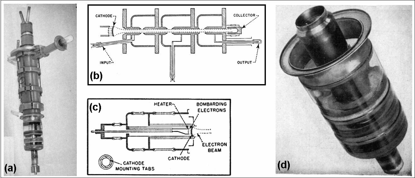
Fig. 10 – 10(a) shows the X-25 with cavities tunable from 1016 to 1056 MHz. 10(b) gives the internal cascaded structure of the family. 10(c) shows details of the tantalum cathode heated by the electron bombardment on its back surface. 10(d) shows the cathode assembly, designed to supply stable emission during its operative life and to be easily replaced after 10000 hours.
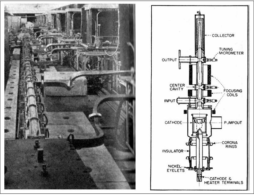
Even more powerful klystrons were designed for high-energy physics applications. The 1-bev linear electron accelerator built at the Stanford Microwave Laboratory around 1953 used 21 three-cavity klystrons, each delivering 17 megawatts 2-microsecond pulses. Beam voltage was pulsed to 295 kilovolts, with 190 amperes beam current. To operate at so high current peaks, the use of oxide coated cathode was mandatory. Cathode assembly was welded with nickel eyelets, to facilitate its removal for cleaning and recoating of the emitting surface. An article with the description of this klystron can be found in Electronics, July 1953. In the picture below an overview of the linear accelerator with klystrons mounted vertically on the right plus a section of the klystron itself.
==========================================================
Bibliography:
- G. C. Southworth, Principle and Applications of Waveguide Transmission, Bell Lab. Series, Van Nostrand
- Klystron Technical Manual, by Sperry Gyroscope Company, Inc., 1944
- K. Henney, Radio Engineering Handbook, McGraw-Hill
- D. R. Hamilton, J. K. Knipp and J. B. Horner Kuper, Klystrons and Microwave Triodes, M.I.T. Radiation Laboratory Series, Vol. 7.
- J. F. Reintjes and G. T. Coate, Principles of Radar, Staff of the Radar School, M.I.T., McGraw-Hill
- E. B. Callick, Metres to Microwaves
- Electronics, October 1951, pages 117-119
- Electronics, July 1953, pages 244 to 248
Some of the U.S. related patents and their release date:
- 2,190,515 W.C. Hahn Ultra Short Wave System 2/13/40
- 2,190, 712 W.W. Hansen High Efficiency Resonant Circuit 2/20/40
- 2,192,048 G.F. Metcalf Electron Beam Device 2/27/40
- 2,220,840 G.F. Metcalf Velocity Modulation Device 11/5/40
- 2,222,901 W.C. Hahn Ultra Short Wave Device 11/26/40
- 2,227,372 Webster and Hansen Tunable Efficient Resonant Circ. 12/31/40
To thank the Author because you find the post helpful or well done.