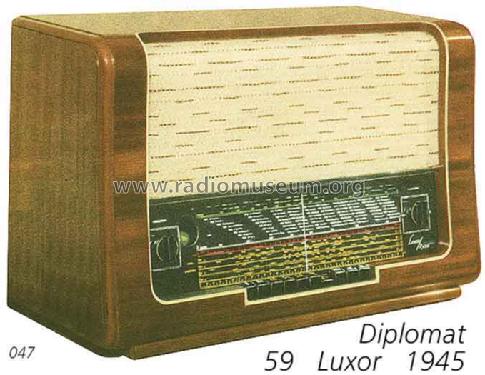
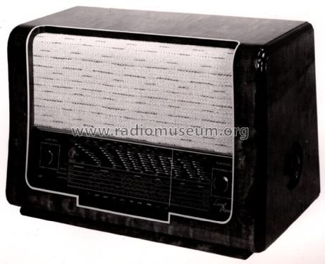
Diplomat 59W
Luxor Radio AB; Motala
- País
- Suecia
- Fabricante / Marca
- Luxor Radio AB; Motala
- Año
- 1945/1946
- Categoría
- Radio - o Sintonizador pasado WW2
- Radiomuseum.org ID
- 18201
-
- alternative name: Luxorita - voir Luxor Radio AB Suède (Sweden)
aukro.cz/radio-luxor-top-stav-7058532442
aukro.cz/radio-luxor-top-stav-7058532442
aukro.cz/radio-luxor-top-stav-7058532442
Haga clic en la miniatura esquemática para solicitarlo como documento gratuito.
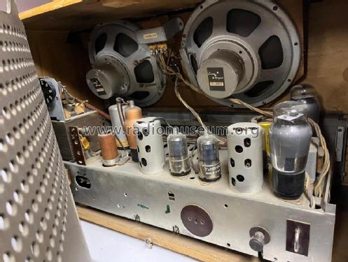
- Numero de valvulas
- 8
- Principio principal
- Superheterodino en general
- Gama de ondas
- OM, OL y más de dos OC
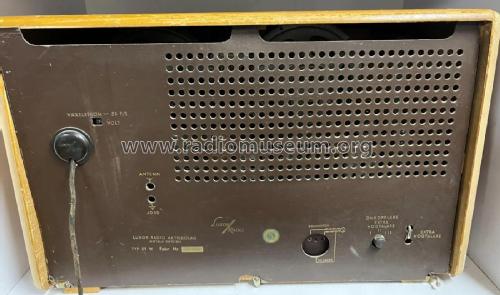
- Tensión de funcionamiento
- Red: Corriente alterna (CA, Inglés = AC)
- Altavoz
- Altavoz dinámico. Se desconoce si a imán permanente o electroimán.
- Material
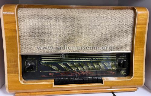
- Madera
- de Radiomuseum.org
- Modelo: Diplomat 59W - Luxor Radio AB; Motala
- Ancho, altura, profundidad
- 620 x 390 x 280 mm / 24.4 x 15.4 x 11 inch
- Anotaciones
- 4 x KW
- Ext. procedencia de los datos
- E. Erb 3-907007-36-0
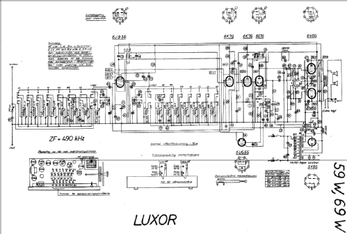
- Referencia esquema
- Die «Thali Schemasammlung» führt das Modell.
- Referencia ilustración
- Das Modell ist im «Radiokatalog» (Erb) abgebildet.
- Otros modelos
-
Donde encontrará 399 modelos, 306 con imágenes y 141 con esquemas.
Ir al listado general de Luxor Radio AB; Motala
Contribuciones en el Foro acerca de este modelo: Luxor Radio AB;: Diplomat 59W
Hilos: 1 | Mensajes: 1
The AF section has a push-pull output stage with a CR-RC-net between preamp and output stage to shift phase. In addition the net is condemned to work as a tone control, too.
Both of the 6V6 get the signal from the plate of the preamp stage. In order to save the phase splitter stage or to evade patents, the model shifts phase with two caps.
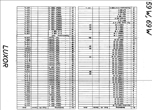
Values of the parts were taken from a friend.'s unit. He also took output power measurements: Full power of 5 Watts at 10% distortion is reached only at 1kHz and switch position R21 grounded. Besides of 1kHz loss of power is dramatic, -4.4dB at 500Hz/3kHz, -6dB at 250Hz/4kHz.
Marc Gianella, 07.Feb.10