- Pays
- Etats-Unis
- Fabricant / Marque
- Philco, Philadelphia Stg. Batt. Co.; USA
- Année
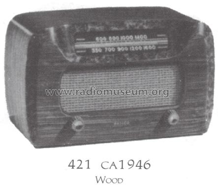
- 1946
- Catégorie
- Radio - ou tuner d'après la guerre 1939-45
- Radiomuseum.org ID
- 50871

Q = ebay objnr : 230096102449
Q = ebay objnr : 230096102449
Q = ebay objnr : 230096102449
Q = ebay objnr : 230096102449
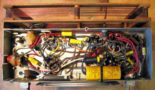
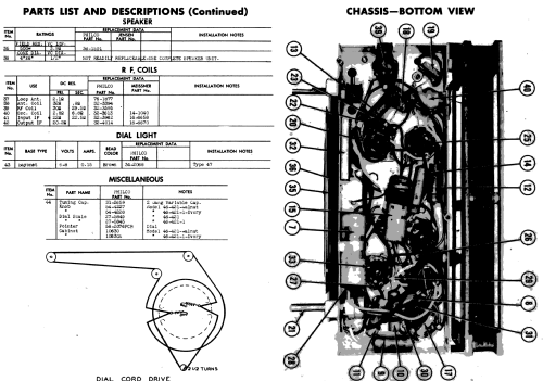
Restored chassis bottom
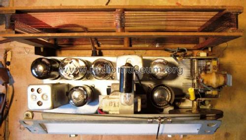
Restored chassis
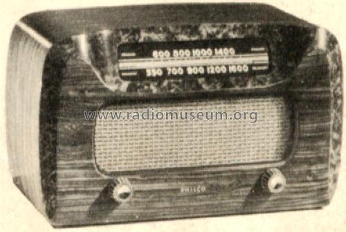
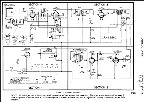
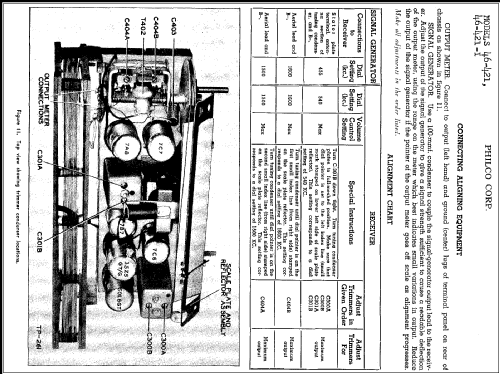
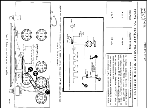
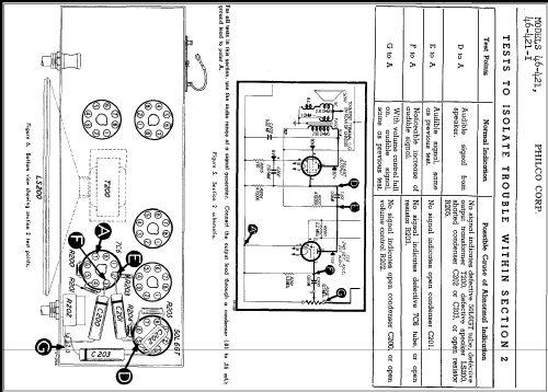
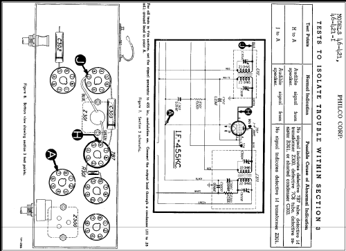
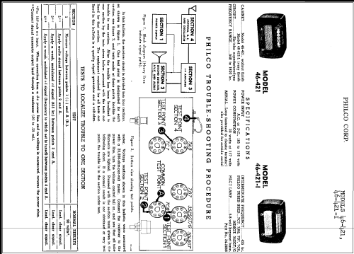
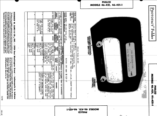
Scanned from the Philco Folder for 1946.
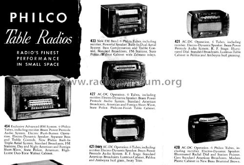
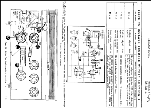
Scanned from the Philco Folder for 1946.
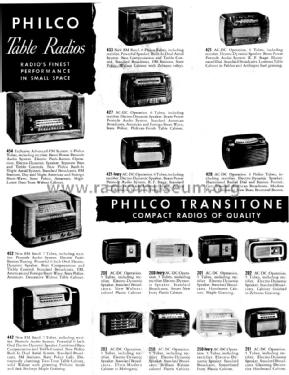
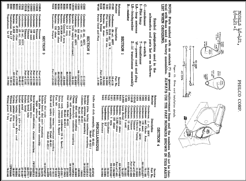
Scanned from the Philco Folder for 1946.
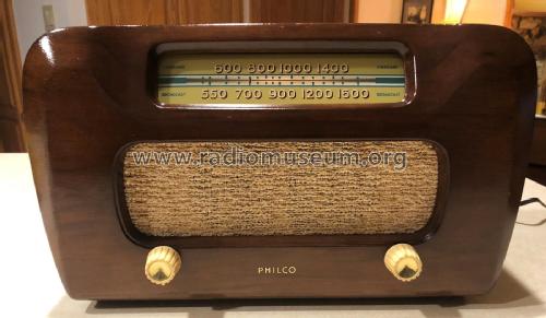
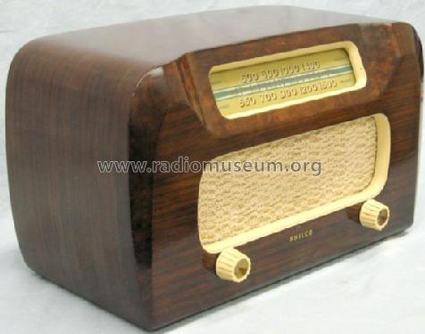
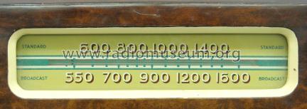
Philco 46-421 Front view
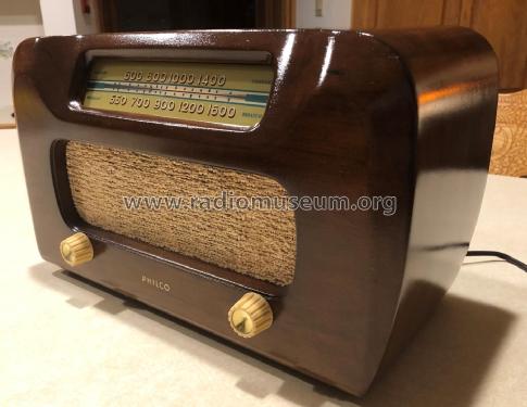
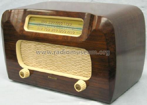
Philco 46-421 Front/Side View
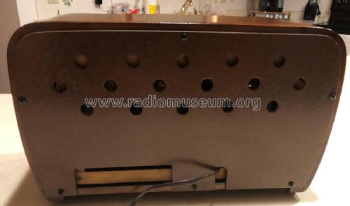
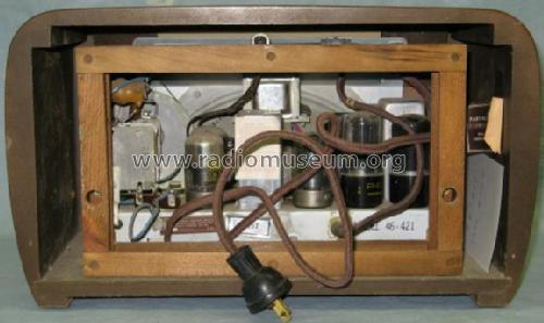
Philco 46-421 Back
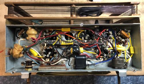
Philco 46-421 chassis after Restoration

Cliquez sur la vignette du schéma pour le demander en tant que document gratuit.
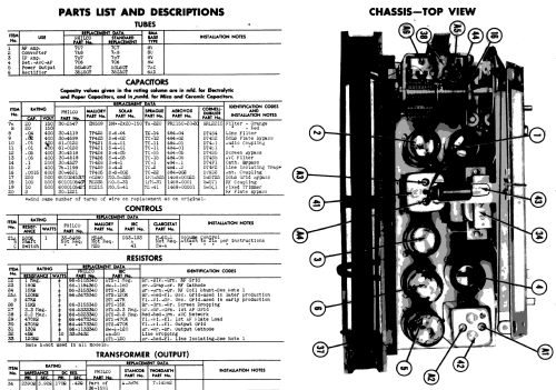
- No. de tubes
- 6
- Principe général
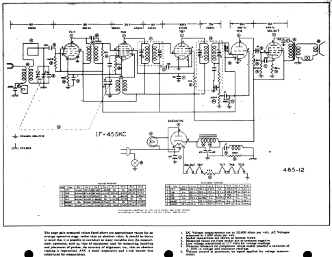
- Super hétérodyne avec étage HF; FI/IF 455 kHz; 2 Etage(s) BF
- Circuits accordés
- 7 Circuits MA (AM)
- Gammes d'ondes
- PO uniquement
- Tension / type courant
- Appareil tous courants (CA / CC) / 115 Volt
- Haut-parleur
- HP dynamique à électro-aimant (électrodynamique)
- Matière
- Boitier en bois
- De Radiomuseum.org
- Modèle: 46-421 - Philco, Philadelphia Stg. Batt
- Forme
- Modèle de table profil bas (grand modèle).
- Remarques
-
Elliptical speaker 4" × 6". Sams photofact folder 465-12 date 10-46 features the Philco models 46-421 and 46-421-1 as the same schematic.
- Source extérieure
- Ernst Erb
- Source du schéma
- Rider's Perpetual, Volume 19 = 1949 and before
- Littérature
- A Flick of the Switch 1930-1950
- Schémathèque (1)
- Photofact Folder, Howard W. SAMS (Folder 465-12 date 10-46)
- Schémathèque (2)
- Machine Age to Jet Age II (page 218.)
- Schémathèque (3)
- Philco Folder for 1946.
- D'autres Modèles
-
Vous pourrez trouver sous ce lien 4006 modèles d'appareils, 2205 avec des images et 3656 avec des schémas.
Tous les appareils de Philco, Philadelphia Stg. Batt. Co.; USA
Collections
Le modèle 46-421 fait partie des collections des membres suivants.
Contributions du forum pour ce modèle: Philco, Philadelphia: 46-421
Discussions: 1 | Publications: 1
How to make a Philco “Special” capacitor.
Philco uses a Special Capacitor that has an inductive series coil added. Philco also uses a special capacitor that has highly inductive qualities engineered in. It is designed to bypass IF to chassis ground. This Philco 46-421 uses one of these as C401. I had to fabricate a replacement. This is how I did it.
To build the coil:
- First acquired a new polypropylene capacitor of 0.2uf 630volts. The high voltage is what I had in stock.
- Use enamel covered magnetic wire. First soldered one end of the wire to one capacitor lead and clipped it short.
- Lay the wire up the middle of the capacitor lengthwise and wrap the coil over top of the magnet wire lead. This holds the wire from slipping.
- Wrap about a 1cm long coil around the out side of the new capacitor.
- Secure the loose coil in place with sticky tape.
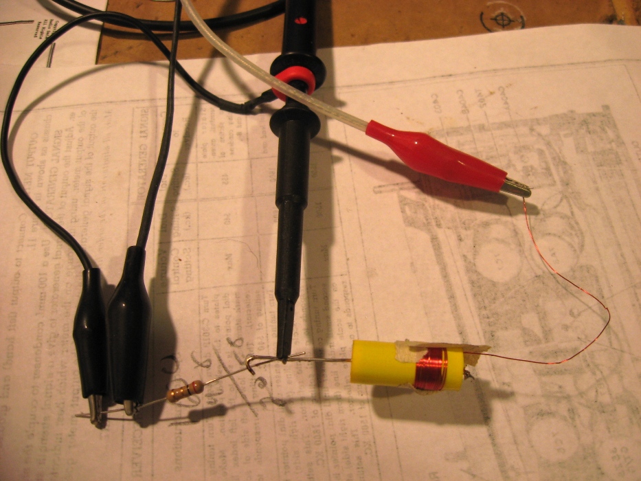
To adjust the coil:
- Connect a 1 or 2 ohm resistor to the free capacitor lead wire. This resistor will generate a voltage to be measured by the oscilloscope.
- Connect the ground lead of the o-scope and signal generator to the loose end of the resistor.
- Connect the o-scope probe to the junction of the resistor and capacitor.
- Connect the signal generator to the loose end of the new coil.
- Set the signal generator for 455 kHz IF frequency.

Adjust the o-scope to display the signal and set an amplitude reference point. The o-scope has a percentage graticule. I set the amplitude for 100%.

Then raised and lowered the frequency. Added or remove coil windings until the signal decreased on either side of 455kHz.

Checked the top end and bottom end frequency at 90% attenuation. Once satisfied with the response replace the sticky tape with heat shrink tubing.

I tried a UL rated safety capacitor with a smaller value but birdies (harmonic interference) appeared across the band. I remade the filter with the original capacitance of 0.2 uf and all the birdies were gone.
Other reference reading can be found on the “Philco Repair Bench” web site. It has a great functional description of Philco’s Special Capacitors.
Happy Fabricating,
Paul
Paul E. Pinyot † 2013, 21.Jan.11