Transistor Radio 8TP1 Ch= 8RT1 tan
Raytheon Mfg. Co.; Cambridge, MA
- Country
- United States of America (USA)
- Manufacturer / Brand
- Raytheon Mfg. Co.; Cambridge, MA
- Year
- 1955 ?

- Category
- Broadcast Receiver - or past WW2 Tuner
- Radiomuseum.org ID
- 69083


Ebay Nr. 320007359226 Bild bearbeitet.
Ebay Nr. 320007359226 Bild bearbeitet.

Ebay Nr. 320007359226 Bild bearbeitet.


ebay.com_204452194686 seller techrewinds
ebay.com_204452194686 seller techrewinds
Click on the schematic thumbnail to request the schematic as a free document.
- Number of Transistors
- 8
- Main principle
- Superheterodyne (common); ZF/IF 455 kHz
- Tuned circuits
- 5 AM circuit(s)
- Wave bands
- Broadcast only (MW).
- Power type and voltage
- Dry Batteries / 4 x 1,5 Volt
- Loudspeaker
- Permanent Magnet Dynamic (PDyn) Loudspeaker (moving coil) / Ø 3.5 inch = 8.9 cm
- Material
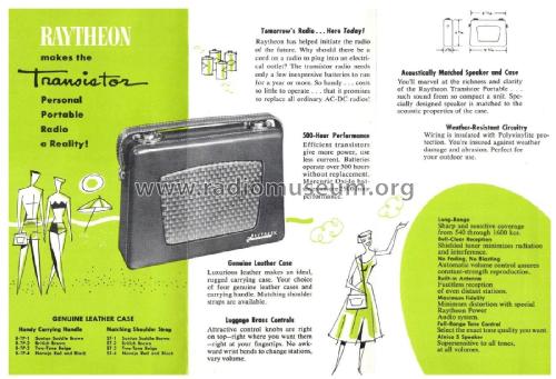
- Leather / canvas / plastic - over other material
- from Radiomuseum.org
- Model: Transistor Radio 8TP1 Ch= 8RT1 [tan] - Raytheon Mfg. Co.; Cambridge,
- Shape
- Portable set > 8 inch (also usable without mains)
- Dimensions (WHD)
- 9.25 x 7 x 2.75 inch / 235 x 178 x 70 mm
- Notes
-
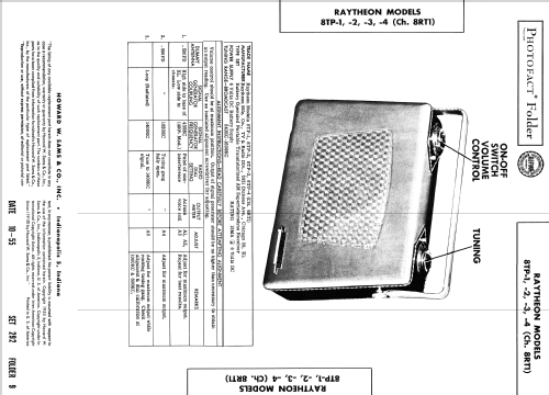
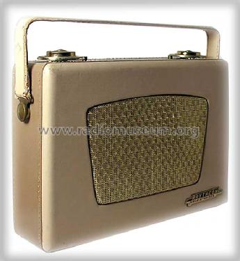
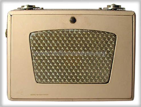
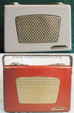
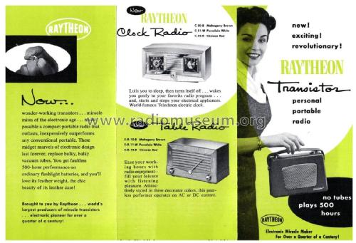
Just a few weeks after Regency (IDEA) has launched the first transistor radio, Regency TR-1 with 4 transistors, Raytheon brought its much bigger 8TP with the models 8TP-1 (tan leather), 8TP-2 (brown leather), 8TP-3 (beige leather) and 8TP-4 (red leather) - all in 1955 and with 8 transistors really outperforming TR1. This was the second transistor radio built in series in the world, followed by SONY models (e.g. TR-55). But the first SONY to appear in the USA was TR-63 in 1957. See also the pocket transistor radios from GE as models 675, 676, 677 and 678 depending in color from 1955. The 8TP1 was immediately followed by a 7 transistor with the same model names!
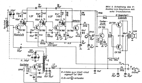
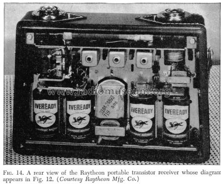
8 Raytheon transistors: 2 of CK761 (oscillator, mixer), 3 of CK760 (IF and detector) and 3 of CK722 for audio (driver, push-pull).
- Price in first year of sale
- 80.00 $
- External source of data
- Ernst Erb
- Mentioned in
- The Collector's Guide To Antique Radios 2. Edition
- Literature/Schematics (1)
- Antique Radio Magazine n.71, March-April 2006, page 35. Article written in Italian
- Literature/Schematics (2)
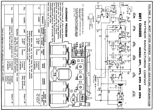
- Photofact Folder, Howard W. SAMS (Set 292 Folder 9 dated 10-55)
- Other Models
-
Here you find 331 models, 153 with images and 247 with schematics for wireless sets etc. In French: TSF for Télégraphie sans fil.
All listed radios etc. from Raytheon Mfg. Co.; Cambridge, MA
Collections
The model Transistor Radio 8TP1 is part of the collections of the following members.
Museums
The model Transistor Radio 8TP1 can be seen in the following museums.
Forum contributions about this model: Raytheon Mfg. Co.;: Transistor Radio 8TP1 Ch= 8RT1
Threads: 1 | Posts: 1
Around the late 1954 Raytheon was fairly ahead in the development of a fully transistorized radio. As reported in Electronics, October 1954, a seven-transistor prototype had been donated to the Massachusetts Governor.
---------

----------
In November 1954 the same magazine gave notice of a four-transistor radio by Regency being in production and available on the market. Texas Instruments supplied the transistor kit for it. See ‘Regency TR-1 - Early announcement’.
Early in 1955 the industrialization of the new radio in Raytheon was proceeding as planned, but they had to maintain their image as leading transistor supplier against TI. They had preferred a no compromise design of the new radio, setting the standard architecture for any future set, with a 455KHz IF, good sensitivity and enough output power with low battery drain. Time had been spent in the design of a lot of new components, suitable for operating with relatively high currents and low voltages, in particular in the design of coils and transformers. Probably to strenghten their image, early in 1955 they launched a relevant informative campaign. In the February 1955 issue of Electronics the production model was announced to be on sale for March 1 at 79.95 USD.
-----------------


-----------
In the March 1955 issue of the same magazine, Raytheon decided to disclose the design of their lab prototypes. The complete schematic diagram and circuit details were given in a three-page article. Here are some pictures of the prototype.

------------
Here is the diagram published in the same article.
The circuit is identical to the one given for production models. The only difference is in the audio output transistors, since in the prototype either CK721 or CK722 could be used, retaining the identical quarter watt max output power. In the text the authors W.E. Sheehan and J.H. Ivers give a lot of circuit details, explaining the reasons of the design choices. All the sections are explained, from the audio amplifier to the IF chain, to the class B transistor detector, whose 10db gain helps to properly drive the AVC circuit, to the oscillator-mixer circuit and components. Authors expect the use of a simple diode detector, provided that the IF gain could be slightly raised in the future. In the actual circuit two 30pF capacitors are used to prevent oscillations in the IF stages.
Also detailed data of the antenna and of the oscillator windings are given in the article, integrated by additional notes in the text. The next table gives a summary of the receiver characteristics.

The new advertising campaign, from Electronics, May 1955, proudly pinpoints the combined offer of transistors and transistorized radios.

Emilio Ciardiello, 21.Sep.09