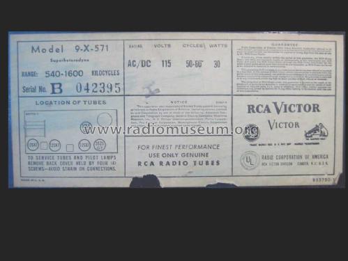
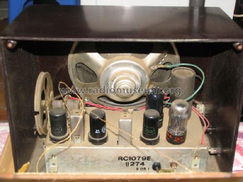
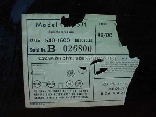
9-X-571 Ch= RC-1079
RCA (RCA Victor Co. Inc.); New York (NY)
- País
- Estados Unidos
- Fabricante / Marca
- RCA (RCA Victor Co. Inc.); New York (NY)
- Año
- 1949
- Categoría
- Radio - o Sintonizador pasado WW2
- Radiomuseum.org ID
- 54105
-
- alternative name: RCA Manufacturing || Victor Talking Machine
Beitman
Rider
Rider

Complete Restoration

Complete Restoration
Complete Restoration
Complete Restoration
Complete Restoration
By Courtesy Of EBAY User: akachuck
Copy gen. von Art Hoch Radio Attic

By courtesy of William Kendrick, USA
By courtesy of William Kendrick, USA
Q = Ebay objnr : 150121826921


By Courtesy Of EBAY User: akachuck
By Courtesy Of EBAY User: akachuck
By Courtesy Of EBAY User: akachuck
By Courtesy Of EBAY User: akachuck
By Courtesy Of EBAY User: akachuck
By Courtesy Of EBAY User: akachuck

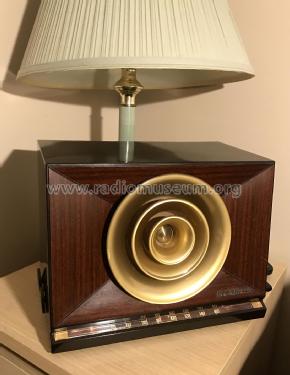
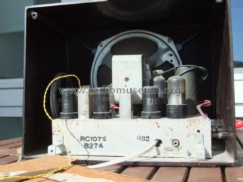
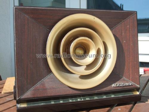
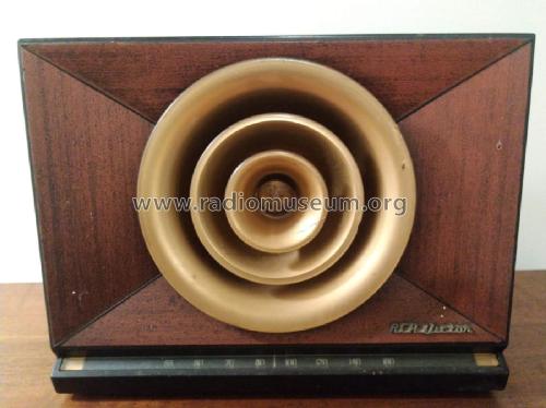
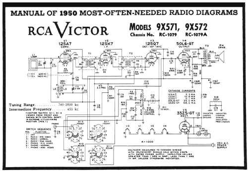
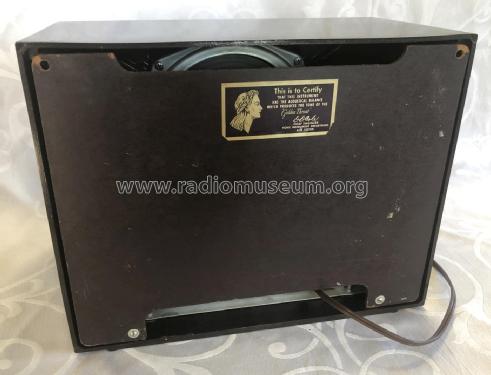
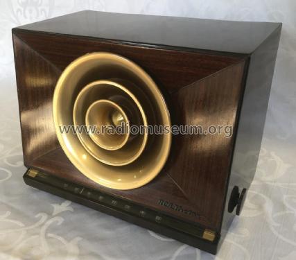
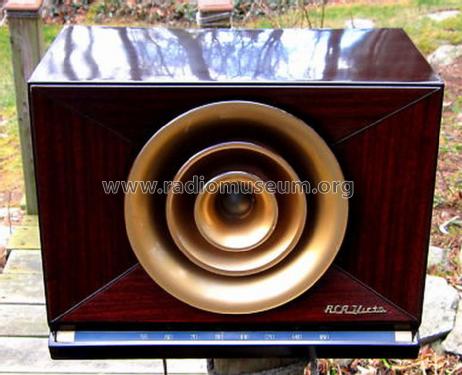
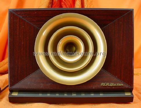
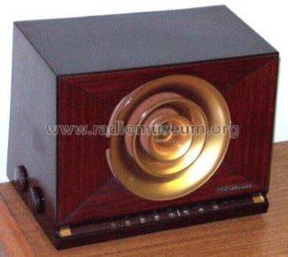
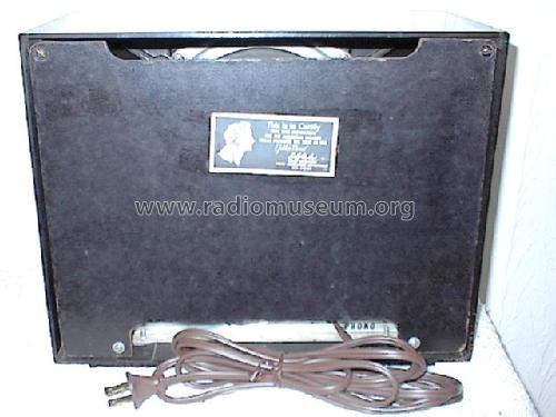
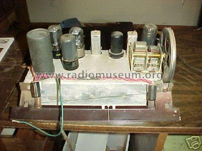
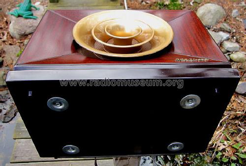
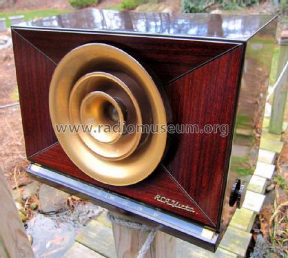
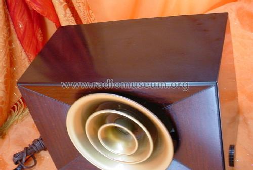
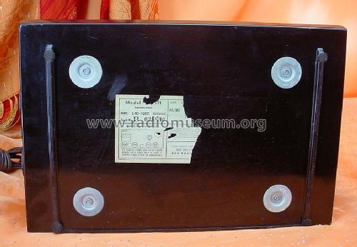
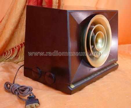
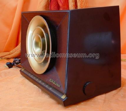
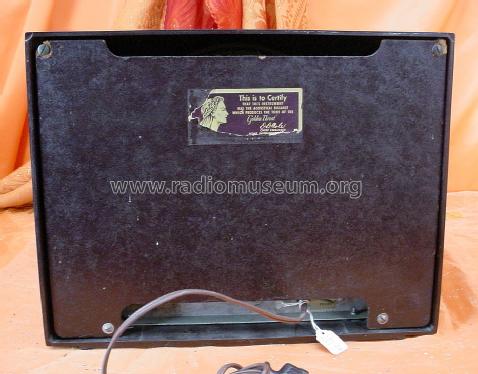
RCA Victor 9-X-571.
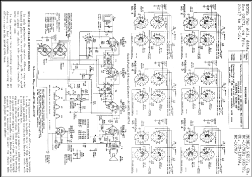
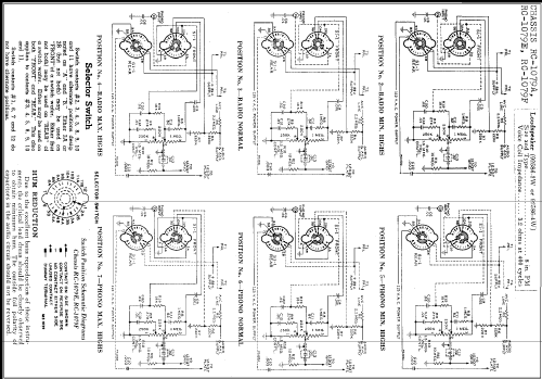
Haga clic en la miniatura esquemática para solicitarlo como documento gratuito.
- Numero de valvulas
- 5
- Principio principal
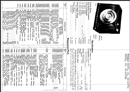
- Superheterodino en general; ZF/IF 455 kHz; 2 Etapas de AF
- Número de circuitos sintonía
- 6 Circuíto(s) AM
- Gama de ondas
- OM (onda media) solamente
- Tensión de funcionamiento
- Red: Aparato AC/DC. / 115 Volt
- Altavoz
- Altavoz dinámico (de imán permanente) / Ø 8 inch = 20.3 cm
- Potencia de salida
- 1.75 W (unknown quality)
- Material
- Bakelita
- de Radiomuseum.org
- Modelo: 9-X-571 Ch= RC-1079 - RCA RCA Victor Co. Inc.; New
- Forma
- Sobremesa de tamaño mediano sin botonera <= 35 cm. (Incluso portables pero sólo con alimantación por red).
- Ancho, altura, profundidad
- 320 x 240 x 210 mm / 12.6 x 9.4 x 8.3 inch
- Anotaciones
- RCA Victor Model 9X-571 shows the color: maroon. Similar model 5-X-572 (#5X572) is in ivory. Dial lamps: 2 Mazda type 1490, 3.2V, 0.16 amp.
- Peso neto
- 4.6 kg / 10 lb 2.1 oz (10.132 lb)
- Ext. procedencia de los datos
- Ernst Erb
- Procedencia de los datos
- The Radio Collector's Directory and Price Guide 1921 - 1965
- Referencia esquema
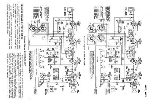
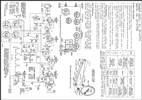
- Rider's Perpetual, Volume 20 covering 1950
- Mencionado en
- Collector's Guide to Antique Radios 4. Edition
- Documentación / Esquemas (1)
- RCA Victor Instruments Service Notes 1949
- Otros modelos
-
Donde encontrará 5118 modelos, 3224 con imágenes y 4152 con esquemas.
Ir al listado general de RCA (RCA Victor Co. Inc.); New York (NY)
Colecciones
El modelo 9-X-571 es parte de las colecciones de los siguientes miembros.
Contribuciones en el Foro acerca de este modelo: RCA RCA Victor Co.: 9-X-571 Ch= RC-1079
Hilos: 1 | Mensajes: 4
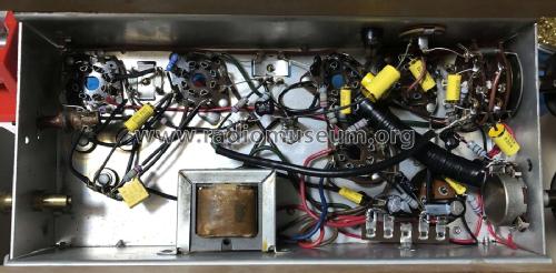
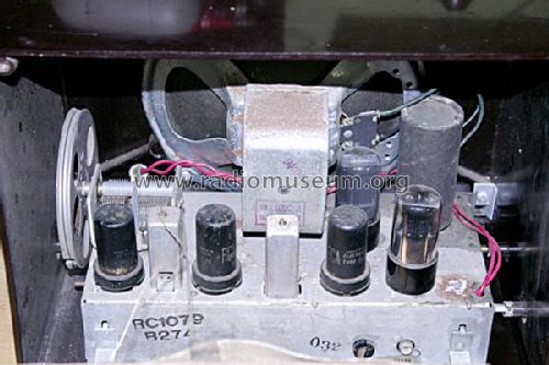
Static during reception with this model is often caused by internal leakage in the IF transformers caused by silver creap in the internal capacitors that causes leakage current between the primary and secondary.
Note: use care when desoldering and soldering to these IF transformer pins because excessive heat will cause the plastic base surrounding the pin to melt and the pin to loosen which can cause internal connections to break.
This leakage can be checked by disconnecting the secondary (both terminals) of the IF transformer. Test one transformer at a time. Temporarily connect the two wires together that were disconnected from the transformer secondary so the remaining radio circuitry will not be an open circuit. Connect a high impedance DC voltmeter, such as a vacuum tube voltmeter or a digital voltmeter, to either of the disconnected secondary terminals. Turn on the radio and check for the presence of any DC voltage reading on the meter. This might be a jumpy reading. A transformer with good capacitors will not have any voltage during this test.
If leakage is found it can usually be eliminated by disassembling the IF transformer and making repairs. Sometimes careful visual inspection will show black wiskers on the mica capacitor sheet between the primary and secondary sides which can be scraped away. Sometimes the mica sheets can be carefully cut or broken to separate the primary side from the secondary side. Sometimes the mica sheet capacitors must be disconnected or removed and replaced by temperature-stable ceramic or mica capacitors.
Paul Moyer, 24.Jan.07