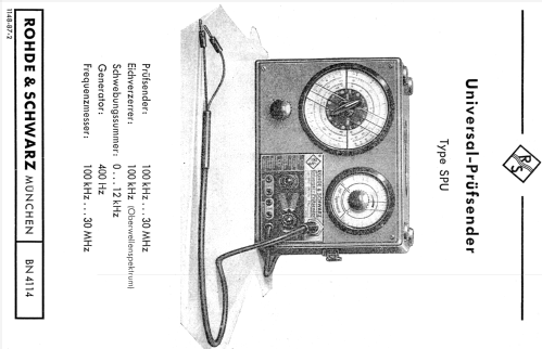
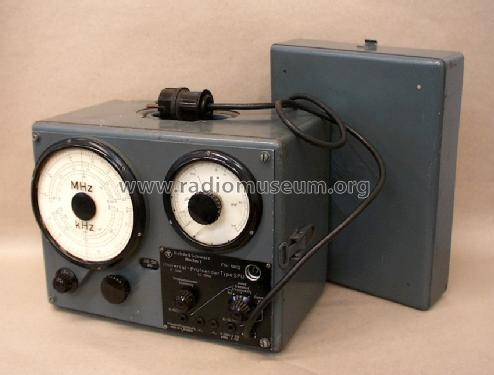
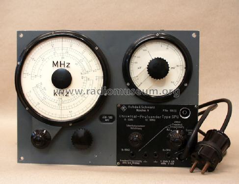
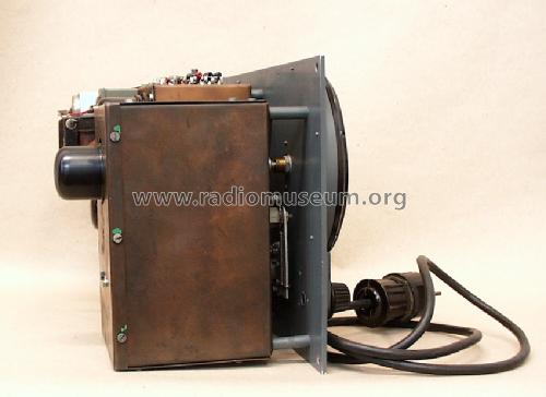
Universal Prüfsender SPU BN4114
Rohde & Schwarz, PTE; München
- Hersteller / Marke
- Rohde & Schwarz, PTE; München
- Jahr
- 1949
- Kategorie
- Service- oder Labor-Ausrüstung
- Radiomuseum.org ID
- 120198
-
- anderer Name: Messgerätebau Memmingen || Physikalisch-Technisches Entwicklungslabor Dr. Rohde & Dr. Schwarz


Klicken Sie auf den Schaltplanausschnitt, um diesen kostenlos als Dokument anzufordern.
- Anzahl Röhren
- 3
- Wellenbereiche
- Wellen in den Bemerkungen.
- Betriebsart / Volt
- Wechselstromspeisung / 110; 125; 150; 220 Volt
- Lautsprecher
- - Für Kopfhörer oder NF-Verstärker
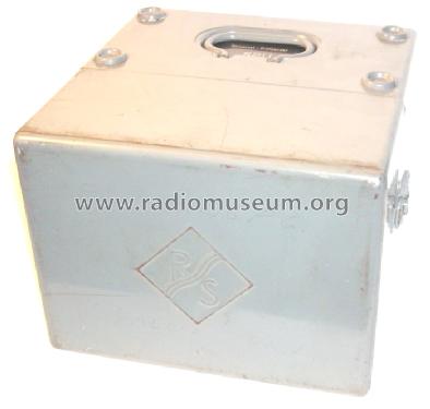
- Material
- Metallausführung
- von Radiomuseum.org
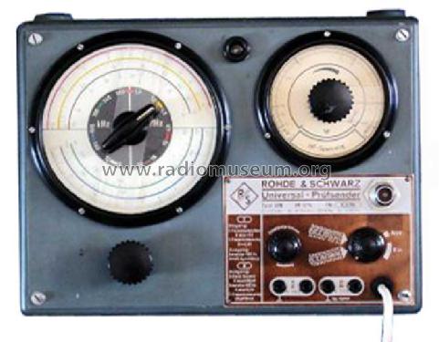
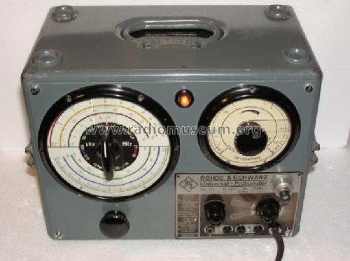
- Modell: Universal Prüfsender SPU BN4114 - Rohde & Schwarz, PTE; München
- Form
- Tischmodell, Zusatz nicht bekannt - allgemein.
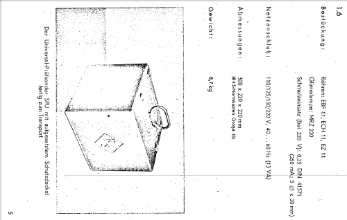
- Abmessungen (BHT)
- 300 x 220 x 200 mm / 11.8 x 8.7 x 7.9 inch
- Bemerkung
- Rohde & Schwarz SPU Universal Prüfsender;
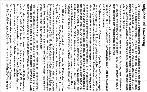
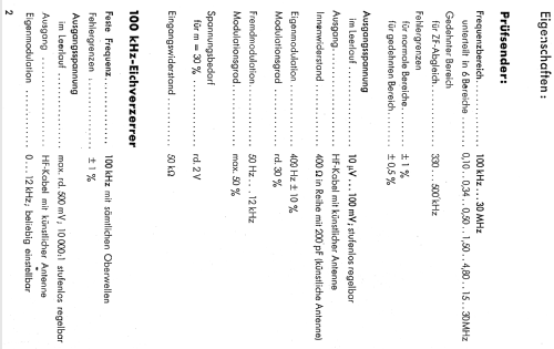
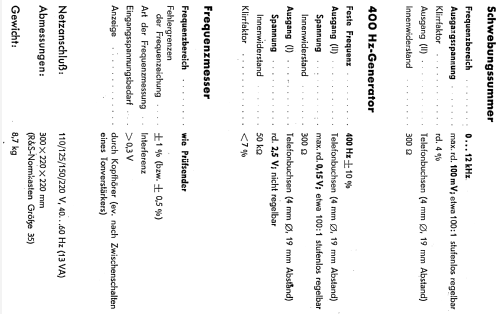
Signalgenerator, NF-Generator 10-12000 Hz; HF 0.1 - 30 MHz, AM-Modulation mit 400 Hz möglich.
- Nettogewicht
- 11.7 kg / 25 lb 12.3 oz (25.771 lb)
- Datenherkunft
- -- Collector info (Sammler)
- Literaturnachweis
- Funk-Technik (FT) (14/1949, S. 426)
- Literatur/Schema (1)
- Radio-Mentor (3/1950, S.126 f., Gerätebericht m. Schema)
- Weitere Modelle
-
Hier finden Sie 543 Modelle, davon 500 mit Bildern und 249 mit Schaltbildern.
Alle gelisteten Radios usw. von Rohde & Schwarz, PTE; München
Sammlungen
Das Modell Universal Prüfsender befindet sich in den Sammlungen folgender Mitglieder.
Forumsbeiträge zum Modell: Rohde & Schwarz, PTE: Universal Prüfsender SPU BN4114
Threads: 1 | Posts: 2
Hello Gentlemen,
After posting the 5 pages of techical data for the BN4114 unit from Archives of the USA offices of R&S, I wish to identify one anomaly with the factory data presented to me.
The front plate of the Signal Generator of the production model which I have in my possession; and the same front panel of the unit from the late member Wesselin Tzenow, depict the small Neon power ON indicator lamp (at the top center of the dial).
One additional item of concern relates to the technical data: since I have a copy of the Technical data folder 1148-87-b and the revised page "b" which pertains to the Output voltages values, there is no correlation to the "added" power ON neon lamp!!
Does any member have the technical data pages beyond page 4 of those sent to me from the USA office of Rohde & Schwarz?
I am preparing to begin the equipment checks to perform an alignment check on my early Argentin-produced Philips AL161 radio which has the IF requency of 175KHz. . . . .it appears as though the technical data states the IF wavelengths as being available from 330Khz up to 500Khz.
Am I seriously mistaken from the technical data??
Respectfully,
Robert
Robert Sarbell † 22.3.22, 17.Jun.11