TR-55
Sony Corporation; Tokyo
- Country
- Japan
- Manufacturer / Brand
- Sony Corporation; Tokyo
- Year
- 1955

- Category
- Broadcast Receiver - or past WW2 Tuner
- Radiomuseum.org ID
- 71238
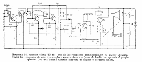


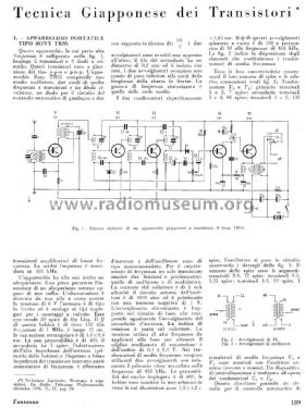
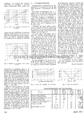
Review "L'antenna" apr 1957.
Review "L'antenna" apr 1957.

Click on the schematic thumbnail to request the schematic as a free document.
- Number of Transistors
- 5
- Main principle
- Superheterodyne (common); 2 AF stage(s)
- Tuned circuits
- 5 AM circuit(s)
- Wave bands
- Broadcast only (MW).
- Power type and voltage
- Dry Batteries / 4 x 1,5 Volt
- Loudspeaker
- Permanent Magnet Dynamic (PDyn) Loudspeaker (moving coil) / Ø 2.5 inch = 6.4 cm
- Power out
- 0.05 W (unknown quality)
- Material
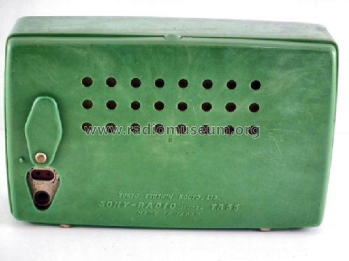
- Plastics (no bakelite or catalin)
- from Radiomuseum.org
- Model: TR-55 - Sony Corporation; Tokyo
- Shape
- Very small Portable or Pocket-Set (Handheld) < 8 inch.
- Dimensions (WHD)
- 5.5 x 3.5 x 1.5 inch / 140 x 89 x 38 mm
- Notes
-
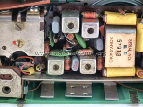
In April 1955 SONY has built a prototype of it's first Transistor Radio, the TR-52, looking like United Nations Building - but TR52 was never really released because of the front-plate "ungluing". This model, TR-55 (TR 55, TR55) has then been produced as the first SONY Transistor Radio for sales in August 1955. TR-55 is a superheterodyne and can also be used with earphone. TR-55 was the first transistor radio produced and sold in Japan. It uses the following transistors: 2T51 (oscillator-mixer), 2 x 2T52 (for IF), 2T53 (AF driver) and 2T12.
The very first commercially produced transistor radio was Regency TR-1 from October 1954 followed by Raytheon 8TP in spring 1955. GE has also built a pocket transistor radio in 1955 as models 675 to 678 depending color. The first SONY imported to the USA was TR-63 in 1957.
- Net weight (2.2 lb = 1 kg)
- 0.6 kg / 1 lb 5.1 oz (1.322 lb)
- Price in first year of sale
- 18,900.00 yen
| Sony Transistor Radio History including TR-55 and TR-5 | 4609 KB |
- Documents regarding this model
- Author
- Model page created by Ernst Erb. See "Data change" for further contributors.
- Other Models
-
Here you find 4072 models, 3929 with images and 976 with schematics for wireless sets etc. In French: TSF for Télégraphie sans fil.
All listed radios etc. from Sony Corporation; Tokyo
Forum contributions about this model: Sony Corporation;: TR-55
Threads: 1 | Posts: 2
Comments on the Circuits of the first Transistor Radios
Translated from: Gebert W Anmerkungen zu den Schaltungen der ersten Transistorradios Funkgeschichte 115 (1997) 241-44 by W Gebert and M Burgess
Wolfgang Gebert, Berlin
Telefunken TR-1 and Regency TR-1
Here we add the following commentary to the article "Telefunken Pocket Radios from 1955-1960" in Funkgeschichte Nr. 113 (1)
In the USA on the 18th October 1954, the "Regency TR-1," developed by Texas Instruments was launched on the market. It was the first mass-produced transistor receiver in the world and arrived earlier than the professional world expected. It was a true international sensation (2).The circuitry of the Regency shows some peculiarities. The circuit of the self-oscillating mixer stage, the base bias voltage of the second IF stage from the AF power stage, the unusual IF of 262KHz and the supply voltage of 22.5 V are all characteristic of the device. Other experimental circuits of the time, as well as the upcoming transistor receivers from 1955 below, deviate from its circuit design significantly.A great similarity is apparent when comparing the circuit of the "Telefunken TR-1" with the "Regency TR-1" (Fig. 1). After the initial pioneering work in the semiconductor factory at Ulm, it is clear that the Hanover factory became active only after the release of Regency receiver. It could be thought of as follows (but unfortunately there are no relevant authorities):They adapted the Regency’s circuit to their available transistors. Because these were pnp types, the supply voltage needed to be reversed. Also since they had poorer RF characteristics, the IF stages were increased to three and the self-oscillating mixer was replaced by separate mixer and oscillator stages. This was necessary to reduce the mixer transistor noise factor. The intermediate frequency was virtually the same. Of course, the RC components to neutralize the IF stages had to be changed. Moreover, they used the same components values, where possible. (There were, however, scarcely any alternatives.) The speaker was similar to the Jensen model used in the Regency.The claim that the development and manufacture of the Telefunken TR-1 took place in the summer of 1954 (3), is probably questionable. Whether a pocket portable was seen behind closed doors at the Hannover Fair in March 1955, is yet to be determined (4).A Regency TR-1 (with Intermetall transistors) would be shown at the Düsseldorf Radio Exhibition in 1955 by Intermetall (6).
Figure 1: Circuit of the "Telefunken TR-1" dated August 55 (top) compared to the "Regency TR-1" from November 54 (bottom). The similarities are obvious. (click on image for full scale schematic)
RCA Development Circuit and the Sony TR-55
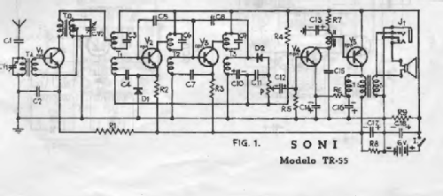
At the beginning of the Fifties interest in Transistor radios did not come from the broadcasting equipment manufacturers. It was the semiconductor manufacturers who wanted to demonstrate the usefulness of their transistors and expand their applications. In particular the Radio Corporation of America (along with Telefunken, both semiconductor and broadcasting equipment manufacturers) had carried out substantial research. RCA showed its first small experimental transistor radio in November 1952 (!), in addition to ten other developmental devices, another in the Summer of 1953 and a third experimental device on or before January 1954. The latter in pocket format. The circuit diagrams of the latter two devices were also published. A comparison of the circuit of the third RCA unit with the Sony TR-55 from August 1955 shows the RCA influence in the RF and IF stages. Using a modified control circuit they replaced the active rectifier with a germanium diode. The altered arrangement of the oscillator, the first IF and the input circuit is determined solely by the fact that the housing of the variable capacitor (the rotors) was grounded (Fig. 2).
I would be very grateful for more information on the theme of "TR-1." I am at w.gebert[A*T]gebert-berlin.de
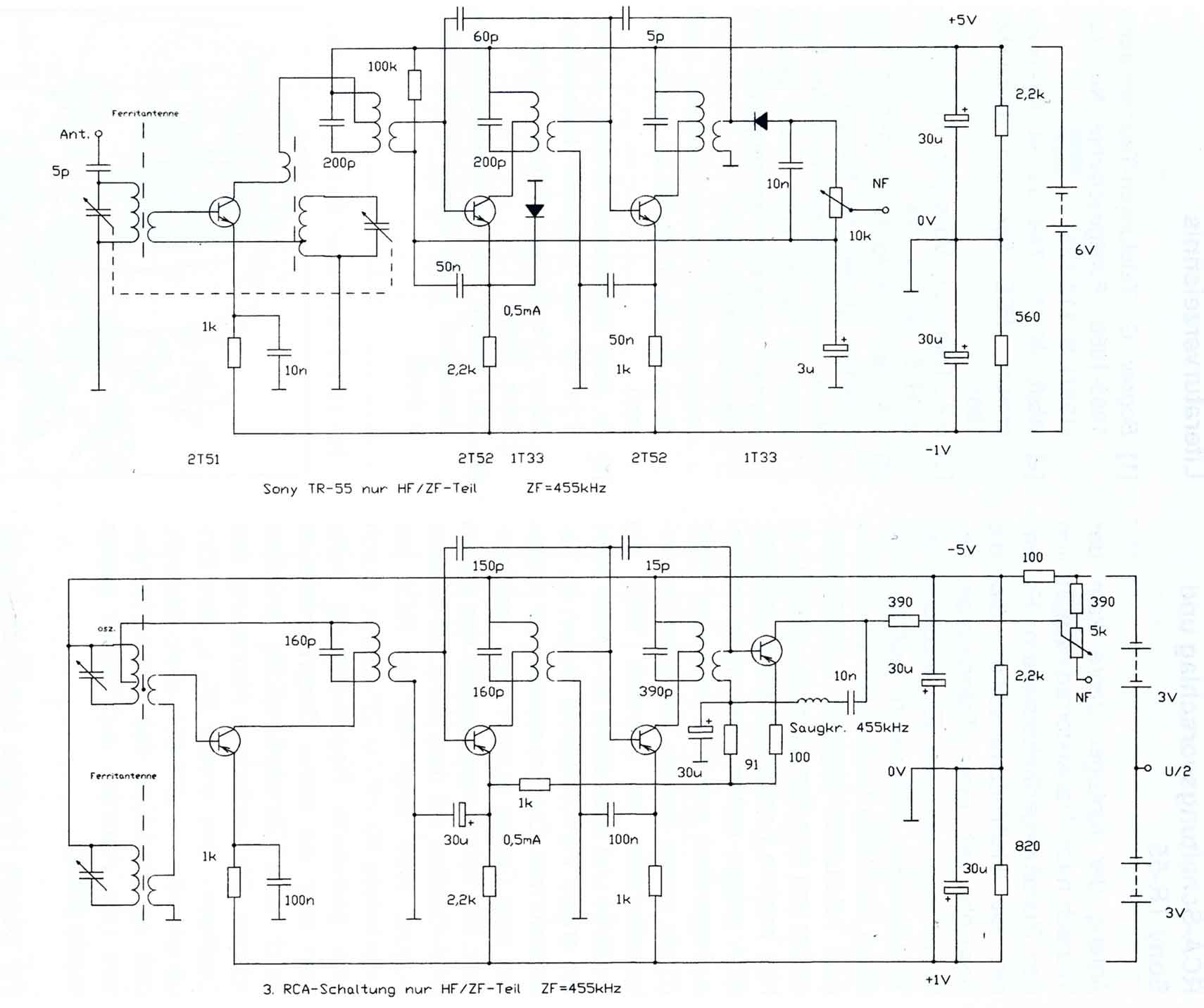
Figure 2 Schematic of the third RCA radio early 54 (bottom) compared to the Sony TR-55, August 55 (top) (click on image for full scale schematic)
Have to ask again stupid:
![]()
This is a "full" - transistor receiver?
References
[1] Bogner, G: Telefunken-Taschenradios 1955-1960. Funkgeschichte No. 113 (1997), p 112-125
[2] Wolff, M F: The secret six-month project. IEEE Spectrum, December 1985
[3] o.A.: Transistor Vollsuper. Funk-Technik H. 5, 1956, p 124
[4] o.A.:Radio Mentor H. 6, 1955, p 299: Editorial "Something really new for the Europe was in the air in Hanover but not even demonstrated: Transistor pocket sets and transistor automotive radios.”(ie Radio Mentor suggests that these could be seen unofficially!)
[5] Dr. Rost: Kristalloden-Technik. 2. Aufl., p 417ff.: VolI-Transistor- Mittelwellen-Super. Verlag von Wilhelm Ernst & Sohn, Berlin[6] o.A.: Bericht über die Funkausstellung Düsseldorf. Radio Mentor H. 10, 1955, p 645ff.
published in Funkgeschichte No.115 (1997) S.241-244
Additional References
Funkschau 5 /1956 p.174-175 Schlegel, H.: Der Transistor-Taschen-Super Telefunken TR1
Proceedings of the IRE 8 /1955, p.662ff Holmes, Stanley, Freedman: A Developmental Pocket-Size Broadcast Receiver Employing Transistors
Electronics 7 /1956 p.120-124 n.n.: Transistor Circuitry in Japan
Further reading on the circuitry of the first transistor radios:
Early Transistor Days (Sony TR-55)
Prototype of Raytheon 8TP, the word's second transistor receiver
Attachments
- Gebert-242-WEB_org (109 KB)
- Gebert-244-WEB_org (92 KB)
Wolfgang Gebert, 03.Aug.12