U84
|
|
|||||||||||||||||||||||||||||||||||||
|
Entradas: 2417 Réplicas: 11
Pin layout
|
|
|
Roddie Rankin
04.Nov.22 |
1
Thank you for your brilliant service. I think the pin diagram given for this valve is wrong. Other sources, and the valve I have in my hands, have the filament on pins 7 and 8. |
|
Jacob Roschy
04.Nov.22 |
2
Hello, there is a lot of confusion about this U84 ! The HMV 1120 schematic diagram shows it as directly heated full wave rectifier, while the HMV 5302 schematic diagram shows it as indirectly heated full wave rectifier. To make the chaos perfect, Babani calls it as half-wave rectifier ! Now which one is correct ? Best Regards, |
|
Roddie Rankin
04.Nov.22 |
3
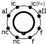
Thank you for your reply, Jacob. i didn't know about the confusion, The U84 I have here (and am about to list on EBay) is a directly heated full-wave rectifier with pins as follows: 1 not connected, 2 not connected, 3 anode 1, 4 not connected, 5 heater common, 6 anode 2, 7 heater 2, 8 heater 1. I have the original Osram box with the Osram valve so it is the real article! all the best. |
|
Stan Roberts
04.Nov.22 |
4
As Jacob implied, the U84 does seem to be an elusive device with seemingly no direct equivalents. Looking at the Mullard publication, "Mullard Valves and Long-Life Television Tubes 1954/5" it suggests using the AZ31 with a base change as an equivalent, see attachment. If nothing else, this should confirm that the U84 is indeed a directly heated full wave rectifier. Kind regards, Stan Anexos
|
|
Jacob Roschy
06.Nov.22 |
5
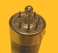
Thank you for the correct U84 pin allocation, Roddie. If possible, could you please upload some detailed photos of your U84 ? We are also looking if someone could upload a correct base diagram ? The U84 seems to be well talented to cause mess, as the “The Valve Museum” is also not correct about the U84 as it tells about the U84 pin allocation: pin 3: a(2) – pin 6: a(1) – pin 7: h,k – pin 8: h. The commonly h = heater and k = cathode at pin 7 would indicate a half-indirectly heated cathode, which seems not to be the case. A possible substitute for the U84 could be the AZ21, also a directly heated 4 V, 1 Amp full wave rectifier, even with B8G base, it only needs some rewiring. Amazingly the AZ21 was mostly used only in Switzerland and to a small degree in Hungary. Best Regards, |
|
Roddie Rankin
06.Nov.22 |
6
Thank you Jacob. I'm sorry to have caused difficulty, but I guess that clearing up the ambiguity may save someone some trouble. I've sent several photos which should enable someone patient to corroborate my understanding of what is going on inside the envelope. I sent them to the page for the valve as this page wants a smaller file than I have and I'm on my iPad which doesn't have a means of reducing file sizes. All the best, Roddie |
|
Jacob Roschy
07.Nov.22 |
7
Thank you Roddie for uploading these many photos, now each detail is clearly visible. I've also made a new base diagram according to your specifications. Best Regards, |
|
Stan Roberts
07.Nov.22 |
8
Jacob, I finally found an old Marconi broadsheet here that lists the U series rectifiers available in probably the mid/late 1940's in UK. I folded it so that it would show the rectifier table alongside the cover with the Marconi name visible. As expected, it confirms your new base diagram pin assignment for the U84. Finally, "The U84 seems to be well talented to cause mess" mystery is over! QED Kind regards, Stan Anexos
|
|
Roddie Rankin
07.Nov.22 |
9
Thank you Stan and Jacob for resolving the uncertainty. That's one less mystery in the world! I'm glad that the U84 I have is the real article! All the best, Roddie |
|
Stan Roberts
07.Nov.22 |
10
My previous attempt omitted part of the table showing the base connection numbers. Hopefully, this table shows them. Stan Anexos
|
|
Jacob Roschy
10.Nov.22 |
11
Thank you Stan for uploading the Marconi broadsheet. It says pins 4 & 5 are internal connected, while Roddie found the heater common at pin 5, - so I took both into account by my redesigned base diagram. Although the U84 and the AZ21 are very similar in construction and have the same heater ratings, their performances are quite different. While the AZ21 can deliver even 120 mA DC at 300 + 300 V AC input, the U84 is only capable of merely 75 mA at 250 + 250 V AC input.
|
|
Roddie Rankin
10.Nov.22 |
12
Thank you for all the further information Jacob and Stan. As a postscript, the Data Manual for my Avo CT160 valve tester corroborates my pin out above with regard to the anodes, pins 1 and 2 not being connected, and in having either end of the heaters on pins 7 and 8. It has asterisks against pins 4 and 5 which means, Avo say, that "an unknown electrode may be connected to this pin internally." So it appears that Avo were aware of different versions of the valve which all had the same anode and heater connections but which differed on pins 4 and 5. All the best. |
Fin de las contribuciones al foro de válvula
| Cumplimiento de datos | Más información |


