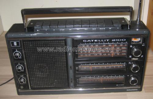
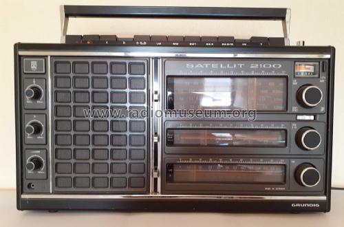
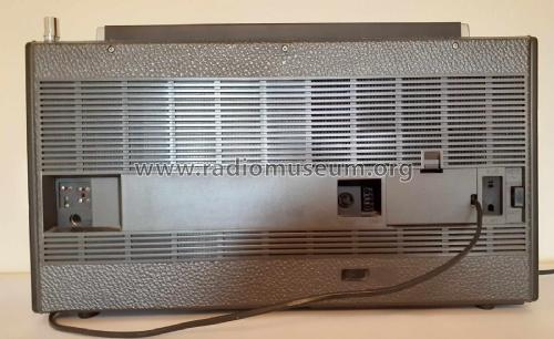
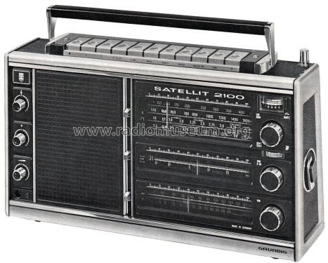
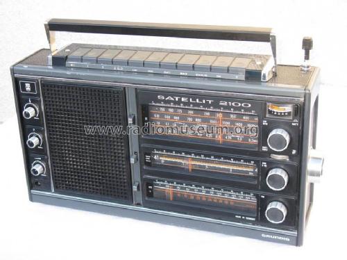
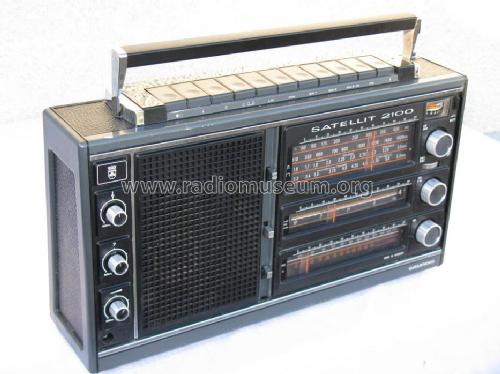
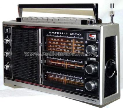
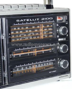
Satellit 2100
Grundig (Radio-Vertrieb, RVF, Radiowerke)
- Country
- Germany
- Manufacturer / Brand
- Grundig (Radio-Vertrieb, RVF, Radiowerke)
- Year
- 1976–1979
- Category
- Broadcast Receiver - or past WW2 Tuner
- Radiomuseum.org ID
- 71607
-
- alternative name: Grundig Portugal || Grundig USA / Lextronix
Q: Grundig, TI 3/76
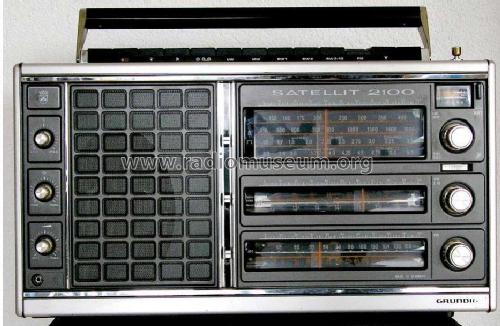
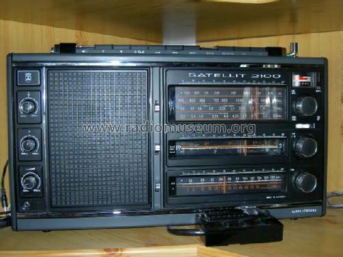
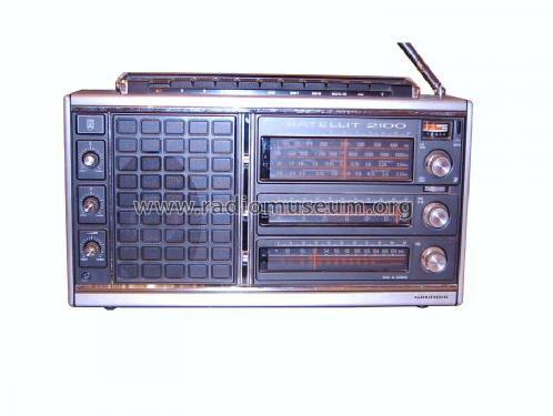
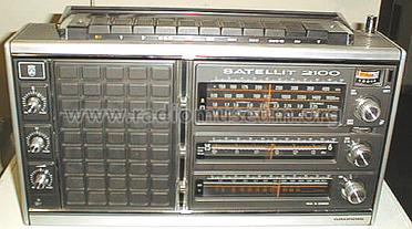
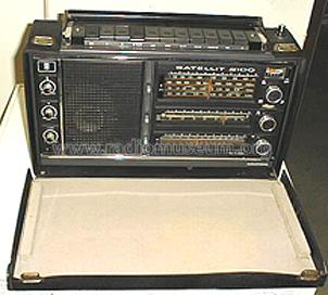
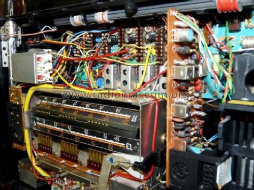
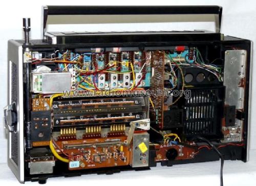
Grundig Satellit 2100
Grundig Satellit 2100
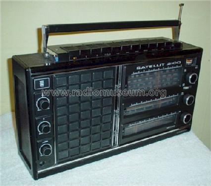
Grundig Satellit 2100
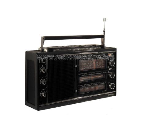
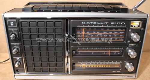
Grundig Satellit 2100
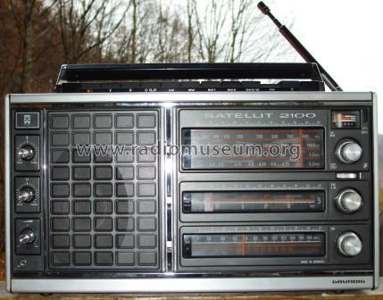
Grundig Satellit 2100
Grundig Satellit 2100
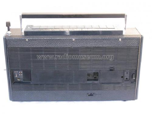
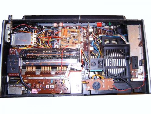
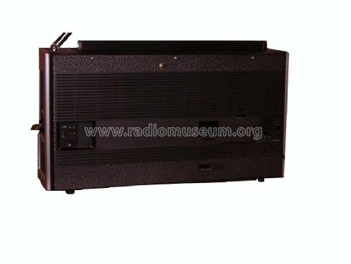
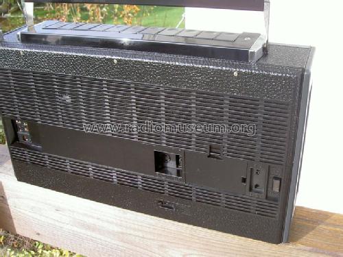
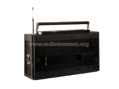
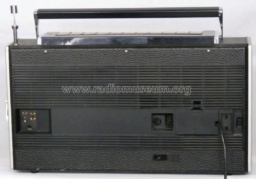
Grundig Satellit 2100 (Rückansicht)

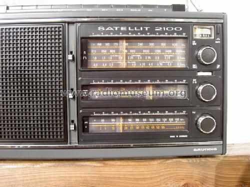
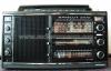
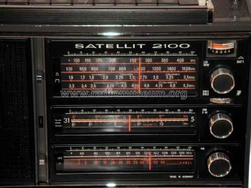
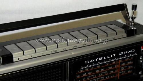
Grundig Satellit 2100 (Skala)
Click on the schematic thumbnail to request the schematic as a free document.
- Number of Transistors
- 27
- Semiconductors
- Main principle
- Superhet, double/triple conversion; ZF/IF 2000/460//10700 kHz
- Tuned circuits
- 13 FM circuit(s)
- Wave bands
- Broadcast, Long Wave, more than 2 x SW plus FM or UHF.
- Power type and voltage
- Line / Batteries (any type) / 110-127; 220-240 / 6×1,5 Volt
- Loudspeaker
- 2 Loudspeakers
- Power out
- 2.5 W (unknown quality)
- Material
- Plastics (no bakelite or catalin)
- from Radiomuseum.org
- Model: Satellit 2100 - Grundig Radio-Vertrieb, RVF,
- Shape
- Portable set > 8 inch (also usable without mains)
- Dimensions (WHD)
- 460 x 270 x 120 mm / 18.1 x 10.6 x 4.7 inch
- Notes
-
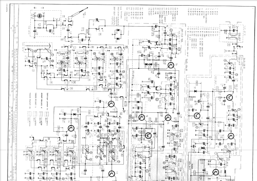
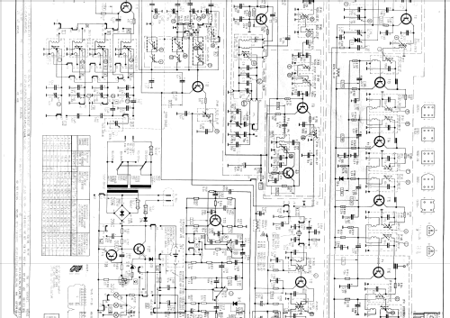
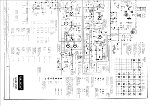
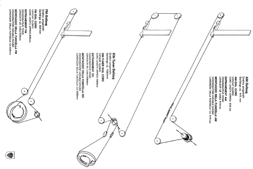
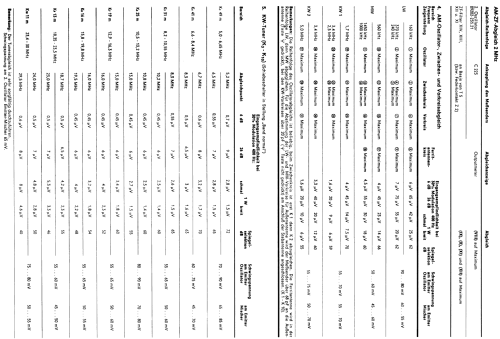
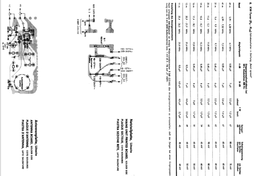
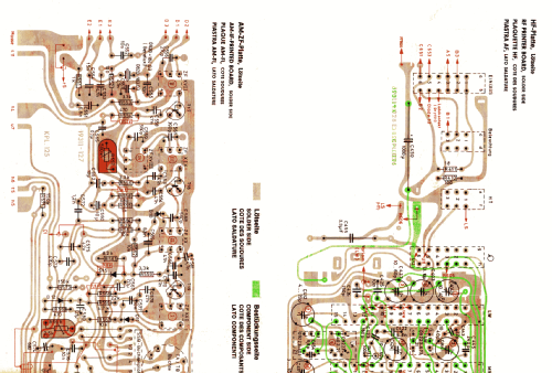
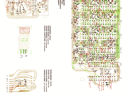
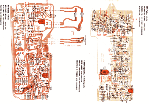
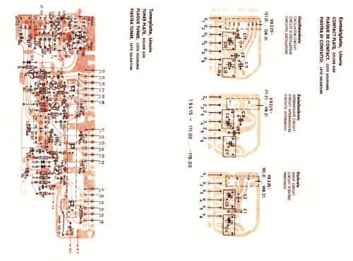
Grundig Satellit 2100: Bandbereiche L, M, K1 (1,6 - 3,5 MHz / 187 - 85 m), K2 (3,3 - 5,2 MHz / 90 - 58 m), K3 - K10 (5 - 50 MHz in 8 etwas überlappenden Bereichen mit schaltbarer Bandspreizung für das 49, 41, 31, 25, 19, 16, 13, 11 m - Rundfunkband).
In den Bereichen L, M, K1, K2 9 Kreise, Einfachsuper; nur in den Bereichen K3 - K10 Doppelsuper mit erster ZF 2 MHz, zweiter ZF 460 kHz, 14 Kreise.
Im UKW-Bereich ZF 10,7 MHz, schaltbare AFC, schaltbarer Hochtonlautsprecher.
Ausgangsleistung bei Batteriebetrieb 2,5 W, bei Netzbetrieb 4 W Sinus, 7 W Musik. Schaltbuchse für externe Speisespannung 9···16 V.
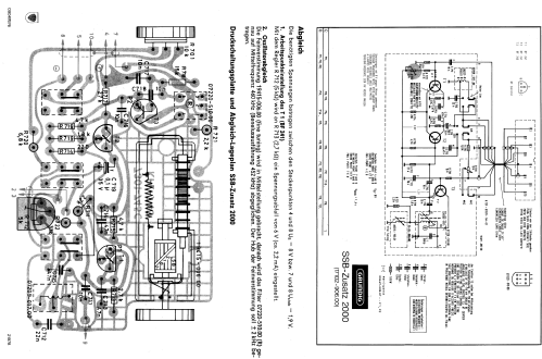
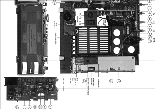
Anschluß für den SSB-Zusatz 2000. Bei der Beneluxausführung beträgt die zweite AM - Zwischenfrequenz 452 kHz statt 460 kHz. Entsprechend muß die Mittelfrequenz des BFO - Zusatzes eingestellt sein.
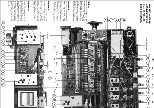
Kosmetisch wurde das Design des Geräts wiederholt etwas verändert:
- erste Ausführung: silberne Drucktasten, feineres Lautsprechergitter
- Profi - Look: Schwarze Drucktasten, feineres Lautsprechergitter
- letzte Ausführung: Satellit 3000 - Look: "waffelförmiges" Lautsprechergitter, silberfarbene Drehknöpfe
- Net weight (2.2 lb = 1 kg)
- 6.3 kg / 13 lb 14 oz (13.877 lb)
- External source of data
- eigene Sammlung
- Source of data
- Handbuch VDRG 1977/1978
- Literature/Schematics (1)
- -- Original-techn. papers.
| Grundig_Kurzwellenfibel_Sattelit_2100_3000 | 4596 KB |
- Documents regarding this model
- Author
- Model page created by Johannes Bernhauser. See "Data change" for further contributors.
- Other Models
-
Here you find 6196 models, 5420 with images and 4191 with schematics for wireless sets etc. In French: TSF for Télégraphie sans fil.
All listed radios etc. from Grundig (Radio-Vertrieb, RVF, Radiowerke)
Collections
The model Satellit is part of the collections of the following members.
- Juan Almagro-Lopez (E)
- Johannes Bernhauser (A)
- Peter Boll (D)
- Martin Bösch (CH)
- Martin Fichtinger (A)
- Rainer Friedrich (D)
- Jörg Holtzapfel (D)
- Winfried Höller (D)
- Dimitrios Karas (GR)
- Rolf Leonhardt (D)
- Vladimir Manannikov (RUS)
- Gianluigi Miazzi (I)
- Ryan Murphy (IRL)
- Manuel Albano Neves (P)
- Elvira Orasch (A)
- Fred Overbeek (NL)
- Jaroslav Pochyly (CZ)
- Museum Roggenhofer (A)
- Fabio Sarcina di Fidio (I)
- Dieter Schulte-Kulkmann (D)
- Sándor Selyem-Tóth (H)
- Alois Steiner (A)
- Francisc VISKY (RO)
- Dominik Wulf (D)
Literature
The model Satellit is documented in the following literature.
Forum contributions about this model: Grundig Radio-: Satellit 2100
Threads: 2 | Posts: 8
Sehr geehrte Sammlerkollegen,
Habe vor einiger Zeit einen Satellit 2100 in kaputtem Zustand bekommen. Äußerlich keine Schäden also ein Objekt für eine Restauration.
Ich habe erstmal die Tastatur repariert, es fehlte ein Feder und der Rand der die Feder hält bei der Schadow Tastatur.
Danach funktionierte die Tastatur ohne weitere Reinigung.
Ich habe es dann noch behutsam ausgeblasen, alle Lämpchen erneuert, die Kontakte des Trommeltuners radiert, ich hatte sogar noch eine neue Antenne aus meiner Kurzwellenzeit... Die Skalen und Nadeln wurden gereinigt
Gerät ist jetzt wunderschön wie neu aber...
Nur bei UKW verzerrt er vor allem im Tieftonbereich. Bei AM scheint es normal zu sein. Habe auch den AUX Eingang ausprobiert, der geht auch einigermaßen.
Es scheint also nur FM diese Verzerrungen zu produzieren.
Beim SAT 1400 habe ich eine Meldung über diesen Fehler gefunden, vielleicht sind die Schaltungen ja ähnlich.
Ich habe die hier downloadbaren Pläne, aber keine Lagepläne und keine Stücklisten von dem Gerät.
Wäre sehr froh wenn mir ein Grundigfan Tips gäbe.
Liebe Grüße und Danke
Michael
Michael Gasperschitz, 17.Apr.12
Hello,
I would like to share an experience with all of you regarding repairs on a Satellit 2100, although this problem/solution will apply to all old radios. I was recently reassembling my Satellit 2100 after doing some recapping and a transistor replacment (L.O. transistor on SW 3-10) when I noticed that LW,MW,SW1 andSW2 were completely silent. I shotgun replaced the L.O. transistor here as well (being to lazy to troubleshoot the circuit!) and the problem persisted. I was very dissapointed as the radio played so well just minutes before. FM,SW3-10 still worked properly. For the next few hours I studied the schematic, tested components looked at waveforms on the scope,(there was clearly no local oscillator) even compared voltage readings with a working set to no avail. In utter desparation, I decided that the only component I hadn't tested was the tuning condenser.I connected my digital ohmmeter to the leads which I disconnected from the switch assembly, and I measured 180 ohms. Rotating the shaft made no changes in the reading. I looked carefully at the stator and rotor and could not understand the 180 ohms. Getting out the most powerful eye loupe I could find, I noticed a few strands of Dendrite (check Google for a definition if you don't know about dendrite) between the stator and frame. compressed air was then liberally applied and the 180 ohms dissapeared... Moral of the story: always clean your tuning condensers before wasting a day troubleshooting!! Good Luck, I hope this helps someone someday! Ross
Ross Hochstrasser, 17.Aug.07