Beehive 11-4V Ch= 11-4
Kriesler Radio Company; Newtown (Sydney)
- País
- Australia
- Fabricante / Marca
- Kriesler Radio Company; Newtown (Sydney)
- Año
- 1946–1948
- Categoría
- Radio - o Sintonizador pasado WW2
- Radiomuseum.org ID
- 239753


Haga clic en la miniatura esquemática para solicitarlo como documento gratuito.
- Numero de valvulas
- 4
- Principio principal
- Superheterodino en general; ZF/IF 455 kHz; 2 Etapas de AF; Reflex
- Número de circuitos sintonía
- 6 Circuíto(s) AM
- Gama de ondas
- OM y OC
- Tensión de funcionamiento
- Red: Corriente alterna (CA, Inglés = AC) / 220; 240 Volt
- Altavoz
- Altavoz electrodinámico (bobina de campo) / Ø 5 inch = 12.7 cm
- Material
- Bakelita
- de Radiomuseum.org
- Modelo: Beehive 11-4V Ch= 11-4 - Kriesler Radio Company;
- Forma
- Sobremesa de tamaño mediano sin botonera <= 35 cm. (Incluso portables pero sólo con alimantación por red).
- Ancho, altura, profundidad
- 250 x 220 x 210 mm / 9.8 x 8.7 x 8.3 inch
- Anotaciones
-
Kriesler advertised this set & other post-war models as a "Sealed Radio". Solder joints were marked to prevent unauthorised servicing & tampering.
Walnut Bakelite cabinet. Also available in various colours for 1 Guinea (£1/1/-) extra. Price in WA for standard Walnut model, £19/8/6.
There are 36 variants of this model:
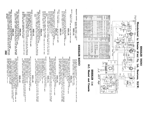
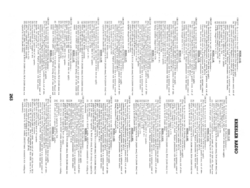
- CIRCUIT: As on 11-4 circuit but with the following alterations:- (Note: Enclosed diagram in lower right hand corner of sheet does not apply).
- Tone control (0.5 Megohm Potentiometer) replaced by 2 position switch, 0.02 μF 600v. condenser (C95) and 0.5 Megohm ½ watt (R117). Disconnect lead from centre lug of potentiometer, and wire it to stationary contact of switch. Earth moving arm of switch. replace potentiometer with fixed resistor.
- Tuning Condenser changed from C3 to C95.
- Coil Kit Unit changed from 15-2 to 15-5.
- 6J8G valve replaced by ECH35 converter.
- R103A (15,000 Ω) was replaced by R153A (40,000 Ω), R136 (30,000 Ω) was replaced by R153B (40,000 Ω).
- COIL KIT: Part No. 15-5 (AWA Tuning Condenser).
- DIAL GLASSES: Part No. 50-22 (Principle section). Part No. 50-25 (Rear glass).
- SPEAKER: Part No. 70-1 (5" Electro dynamic).
- OUTPUT TRANSFORMER: Part No. 18-28.
- POWER TRANSFORMER: Part No. 18-27 (H.T.: 325v each side of centre tap)
PROCEDURE FOR REMOVING CHASSIS FROM CABINET:
- Remove knobs.
- Invert receiver.
- Remove base by breaking seal and unscrewing 4 x 3/16" screws in base of cabinet.
- Remove 4 x 3/16" nuts, situated in the inside corners of the chassis.
- Lay receiver on its back with spindles facing upwards.
- Place one hand each side the of chassis. With the forefingers, exert a downward pressure on the front panel, at the same time withdrawing the chassis from the cabinet.
CHASSIS NUMBERS:
Every receiver that leaves the Kriesler factory is given two chassis numbers.
The "Production" chassis number is stamped on a card. The card is riveted to the main chassis in such a location that the number is able to be read without removing the chassis from the cabinet. The "Production" chassis number is the number that should be quoted, together with the model number, when making enquiries.
The second chassis number (Prefix "0") is stamped into the metal chassis to provide a permanent record.
Both the abovementioned chassis numbers are recorded at the factory.
- Precio durante el primer año
- 18.90 AUS £
- Referencia esquema
- Australian Official Radio Service Manual Vol. VI
- Documentación / Esquemas (1)
- - - Manufacturers Literature (Kriesler Technical Service Instructions.)
- Documentación / Esquemas (2)
- Australian Official Radio Service Manual AORSM (Volume 5, 1947, Page 188 & Volume 6, 1948, Page 262.)
- Autor
- Modelo creado por Konrad Birkner † 12.08.2014. Ver en "Modificar Ficha" los participantes posteriores.
- Otros modelos
-
Donde encontrará 895 modelos, 440 con imágenes y 435 con esquemas.
Ir al listado general de Kriesler Radio Company; Newtown (Sydney)
Colecciones
El modelo Beehive es parte de las colecciones de los siguientes miembros.