SABA S-455WK 455WK
SABA; Villingen
- Country
- Germany
- Manufacturer / Brand
- SABA; Villingen
- Year
- 1938/1939
- Category
- Broadcast Receiver - or past WW2 Tuner
- Radiomuseum.org ID
- 6658
-
- Brand: Schwer & Söhne, GmbH
Knoll

Knoll


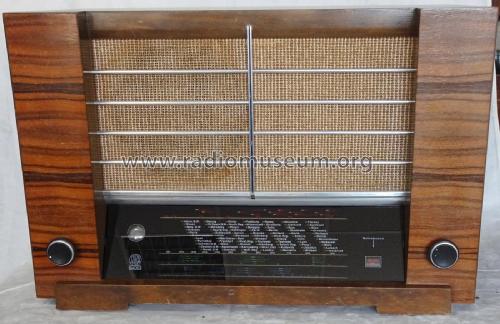


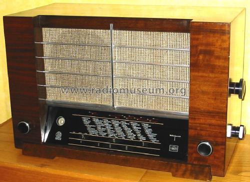
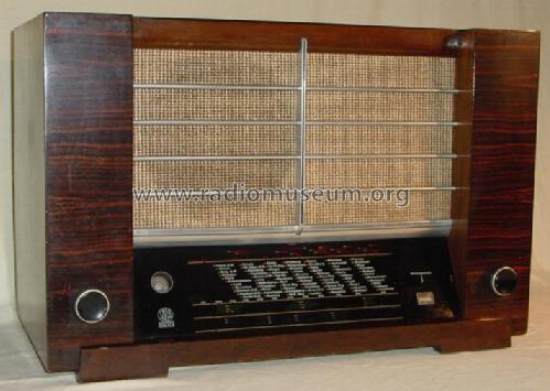
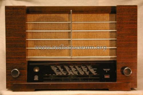
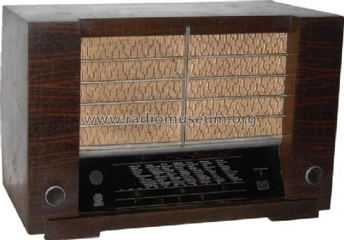
Saba 455WK_Front
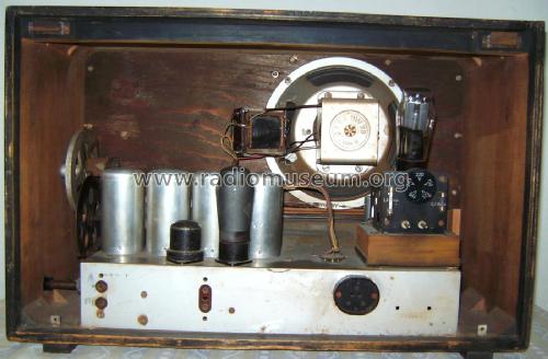
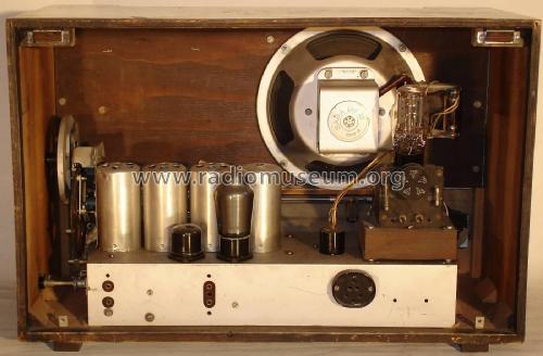
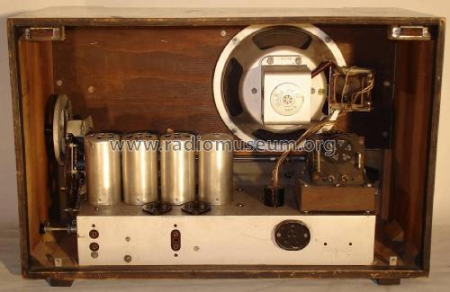
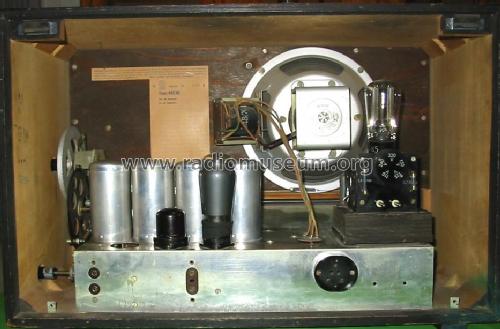
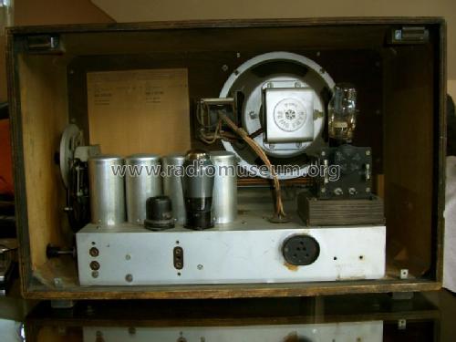
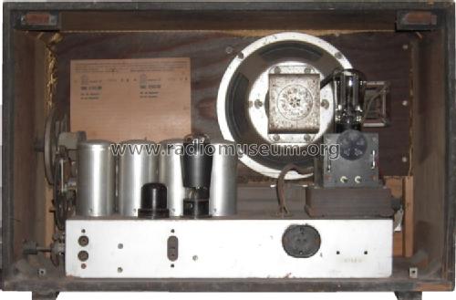
Saba 455WK_innen
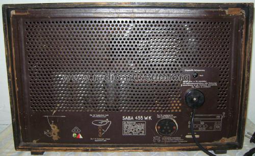
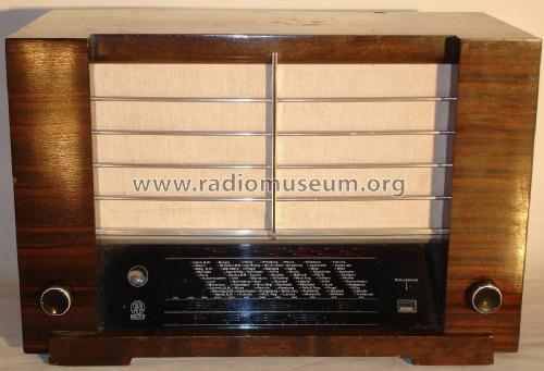
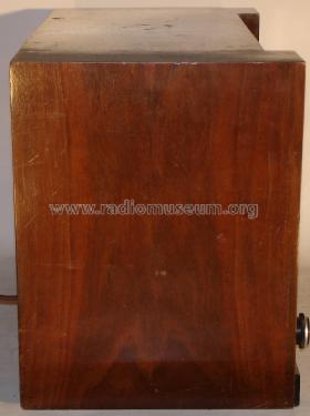
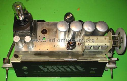
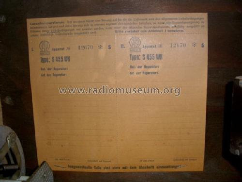
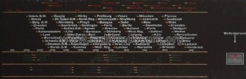
Saba 455WK_RW


"Vier-Zylinder-Radio"
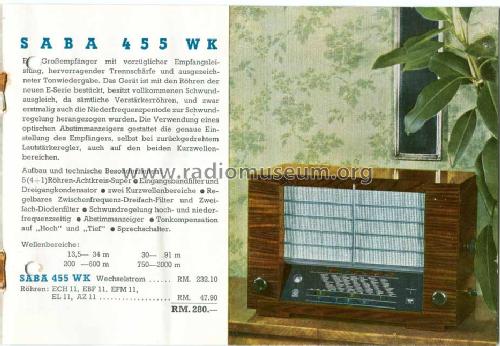
Originalprospekt Saba für Jahrgang 1938/39


Click on the schematic thumbnail to request the schematic as a free document.
- Number of Tubes
- 5
- Main principle
- Superheterodyne (common); ZF/IF 487 kHz
- Tuned circuits
- 8 AM circuit(s)
- Wave bands
- Broadcast, Long Wave and 2 x Short Wave.
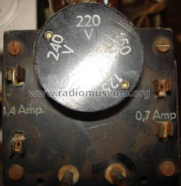
- Power type and voltage
- Alternating Current supply (AC) / 110; 125; 150; 220; 240 Volt
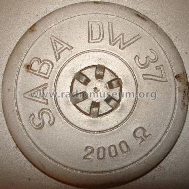
- Loudspeaker
- Electro Magnetic Dynamic LS (moving-coil with field excitation coil)
- Material
- Wooden case
- from Radiomuseum.org
- Model: SABA S-455WK 455WK - SABA; Villingen
- Shape
- Tablemodel, low profile (big size).
- Dimensions (WHD)
- 580 x 380 x 290 mm / 22.8 x 15 x 11.4 inch
- Notes
- Normally we don't put the maker into the model name and tell not to search inclusive maker name in the model name field. Here SABA 455WK instead of just 455WK or 455 WK stands as an example - just to give you this information.
Eingangs-Bandfilter, variable Bandbreitenregelung (ZF).
- Net weight (2.2 lb = 1 kg)
- 16.5 kg / 36 lb 5.5 oz (36.344 lb)
- Price in first year of sale
- 280.00 RM
- Source of data
- Handbuch WDRG 1938 / Radiokatalog Band 1, Ernst Erb
- Circuit diagram reference
- Lange+Schenk+FS-Röhrenbestückung
- Mentioned in
- Technisch- Commercieel - Radio Vademecum Staleman
- Literature/Schematics (1)
- -- Original-techn. papers.
- Picture reference
- Das Modell ist im «Radiokatalog» (Erb) abgebildet.
- Other Models
-
Here you find 1651 models, 1509 with images and 1190 with schematics for wireless sets etc. In French: TSF for Télégraphie sans fil.
All listed radios etc. from SABA; Villingen
Collections
The model is part of the collections of the following members.
Forum contributions about this model: SABA; Villingen: SABA S-455WK 455WK
Threads: 5 | Posts: 15
Ein sehr schöner SABA 455 von 1938, ohne Empfang. Das ist schon ein sehr besonderes Radio.
Wunsch des Besitzers: UKW Empfang, damit er wieder Radio hören kann. Der Besitzer ist kein Sammler, er möchte nur sein Radio, welches er schon ewig in Besitz hat, wieder als Radio betreiben können. In Österreich sind die SABAs ja eher selten anzutreffen. Ein befreundeter Kollege bat mich den Umbau zu machen.
Anforderung: Das Radio sollte nun UKW können - UKW Empfang nun auf Stellung Phono. Abstimmung über den Abstimmknopf mittels Schwungrad. Keine weiteren Veränderungen am Radio. Besitzer will nur UKW. Weiter neue Umbauten sind ja dann immer noch möglich, wenn gewünscht.
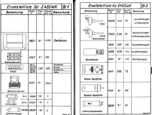
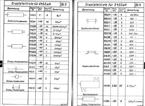
Das Gehäuse ist in einem exzellenten Zustand. Netzteil Elko und Folien -Kondensatoren wurden erneuert. Axiale schwarze Neuware, welche wie die originalen schwarzen Saba Kondensatoren aussieht. Hier muss bei Saba in der Liste (hier bei den Unterlagen) nachgesehen werden, welcher Kapazitätswert zu welcher Teilenummer gehört. Die defekten Glimmerkondensatoren in den Bandfiltern wurden belassen. Hat hier keinen Sinn, Zeit und Mühe zu investieren, da ja in Österreich auf MW nichts mehr reinkommt, welches für Normalbürger (Keine Radiosammler, mit Antennen) von Interesse ist.
Die Skala und der Licht Difussor wurden abgebaut und vorsichtig gereinigt. Hier war der Staub von Jahrzehnten vereiwigt.
Die nicht mehr originalen, defekten Skalenlampe wurden entfernt .
Den Licht Diffusor aus Karton wollte ich erhalten. Die aufwändige Befestigung mit Ösen und Federn ist schon bemerkenswert.
Die Originalen Soffitten in 6V/300mA sind nicht mehr erhältlich.
Neue Ware aus dem KFZ Bereich mit 5W ist zu stark. 2 KFZ 6V Lampen mit je 5W da sind wir bei über 1.6A, das ist Überlastung des Trafos.
Daher wurden E10 LED Lampen (Warmweiß) eingebaut. Mit Gleichrichter und Elko. Die LEDs sollen nicht mit Wechselstrom betrieben werden. Der Gleichrichter ist auch eine Montagehilfe zum Anlöten an die Soffitten Fassungen. Wer will kann das ja wieder rückbauen.
Mit der Größe des Elkos kann die Helligkeit der LED etwas beeinflusst werden.

Damit hat die Skala nun wieder eine vernüftige Beleuchtung.
Die Abstimmung mit Schwungrad ist toll gelöst, hier hat SABA nicht gespaart.

UKW Tuner: 87.5 – 108Mhz
Der Tuner wird fix am Chassis angebaut – nicht außen oder innen am Gehäuse. Es werden nur vorhandene Bohrungen am Chassis verwendet.
Der Drehkondensator wird von Saba mit einem großen Rad angetrieben, hier sind große Löcher vorhanden, in die man Mitnehme einsteckt,
welche dann das Poti für die UKW Abstimmung antreiben. Die Kopplung greift hier lose in das Rad ein.
Das neue Poti für die Abstimmspannung wird an den Drehkondensator Abtrieb (große Pertinax Scheibe) angekoppelt. Die Drechachsen von Drehko und dem Poti sollten dann in der Flucht sein.
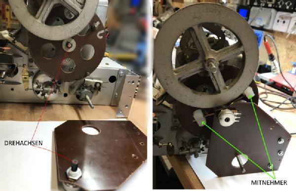
Ein Aluwinkel wird an die vorhanden Löcher des Chassis verschraubt. Dieser trägt das Poti. An der Potiachse sind zwei Mitnehmer, welche lose mit Kunstoffblöcken in die große Scheibe des Drehkos eingreifen. Die Mitnehmer haben genug spiel, dass keinerlei Verspannungen an das Pertinax Rad wirken können.

Ein Kunstoffblock wird mit einem Plättchen und einer Schraube gegen herausfallen gesichert (SP)
Auf der anderen Seite des Chasis wird er eigentliche Tuner mit Netzteil montiert.
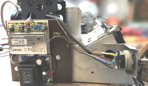
Hier ist es einfachsten einen eigenen Trafo zu verwenden, am wenigsten Eigriff in das Radio. Die NF wird an die Phono Buchsen geliefert. Vom Abstimmpoti geht eine 3polige Leitung zur Platine. Antenne direkt am Tuner.
Der Tuner wird nicht klassisch mit einer Abstimmspannung abgestimmt, es wird eine Spannung am Schleifers des Potis von der CPU digitalisiert, welche dann dem Tuner als Abstimmanweisung digital übermittelt wird. Der Tuner war als Surplus Angebot lange für kleines Geld im Angebot. Einziger Nachteil er braucht 200mA bei 5V. Dafür ist auch der Stereodecoder integriert. Also der Tuner ist Tuner+Zf+Stereodecoder in einem.
Sendereinstellung via dem normalen Skalenantrieb. Keine externen Netzteile. Keine Zusatzverkabelung. UKW wird nun über den Phono Eingang wiedergegeben.
Hier habe ich einen Philips Tuner, dazu eine eigene Platine mit CPU welche den Tuner steuert eingebaut. Im Internet leicht zu finden als „FM1216“ Projekt. Einzig die Software der CPU habe ich etwas modifiziert, da das Abstimmrad nicht den gesamten Drehbereich des Potis von 270 Grad bestreicht. Damit kann die gesamte Skallenbreite für den Bereich von 88.5 - 108MHz genutzt werden.
Von der Antennenbuchse wird hinten am Gehäuse etwas Litze als Wurfantenne herausgeführt.
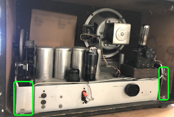
Rückansicht Chassis ohne Rückwand. Die neuen Teile sind grün markiert. Rechts der eigentliche Tuner, Links die Mechanik für das Abstimmpoti. Im Gehäuse war dafür genug Platz. Das Chassis bildet damit eine Einheit, keine zusätzlichen Module sind zu beachten. Der Tuner ist mit dem Radio immer gemeinsam eingeschaltet,
Mit dem UKW Tuner hat das Radio wieder eine Aufgabe im täglichen Leben des Besitzers gewonnen.
Meiner bescheidenen Meinung nach mache ich solche Einbauten in der Form, dass das Radio nicht mit zusätzlichen Tasten, Schalter und Displays ‚belästigt‘ wird, es ist ja ein Gerät aus 1938 mit einem stolzen Alter. Auch das dazustellen von Kästchen und Stecker Netzteilen suche ich zu vermeiden. Das Radio soll mit seiner neuen Funktion, wieder als 'unteilbare' Einheit funktionieren. Ein Aufkleber oder Anhänger an der Rückwand informiert über die neue Empfangsmöglichkeit, damit kann eine eventuelle Entsorgung aus Unkenntnis verhindert werden.
Viele Grüße
H.Stummer
Heinrich Stummer, 25.Apr.22
Hallo
Kann mir jemand sagen, wie man die Abschirmbecher der Schwingkreise abbekommt,
einfach abziehen? Ich möchte dabei nichts kaputtmachen und frage deshalb lieber mal herum.
Mit bestem Dank und freundlichen Grüßen
Knut
Knut Hage, 17.Sep.08
Hallo,
ich such für meinen 455WK eine Rückwand ohne Netzstecker und einen Satz Original Knöpfe zu dem Gerät.Vielleicht hat ja noch jemand sowas auf Lager liegen?
Viele Grüsse aus dem Westerwald
Martin
Martin Schmidt2, 20.Mar.07
The translated output (using the Babelfish software translator) is as follows:
WE LEADING FORWARD: SABA 455WK
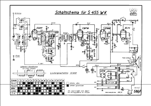
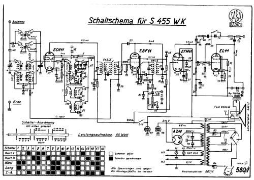
Superhet - 8 circuits - 5 Tubes
Wave bands: 13.5 - 34, 30,-91, 200 - 600, 750 - 2000 m
IF - 485 kHz
As alternating current equipment available
Tube assembly: ECH11, EBF11, EFM11, EL11, AZ11
Power absorption: 55 Watts Connection for 2 loudspeakers: Impedance about 7000 ohms
Special characteristics: Two-stage entrance band filter; even a three-stage and two-stage IF band filter; Three-gang variable tuning capacitor
Range automatic controller (change of coupling with the 1st IF bandfilter), with tone quality automatic controller combined: Language - music switch: Volume control before the 1st NF stage
Three-fold decrease reconciliation, on mixer-, IF- and NF stage working co-ordination
Tuning indicator in form of a magic eye
Wood housing: Electro-dynamic loudspeaker
The use of steel tubes became as well known first only for alternating current receivers and for such over Rm. 285,00 and/or RM. 280.00 retail price approved, because it was not possible to produce from these new tubes in the first year so much that an indiscriminate assembly of the receivers would have been feasible. It would be however nothing wronger than that to want to conclude from the restriction of the steel tube price groups higher on the devices that this kind of tube would be applicable evenly only for the expensive receivers! In the opposite, straight for the receivers of low and middle price classes, will steel tubes the great importance attain, are nevertheless possible it with their assistance not to increase the achievement of these devices inconsiderably without for this higher expenditures would have to be made. An interesting example for this is the steel tubed Superhet Saba 455 WK, which niedrigst to permissible steel-tubed receiver price on the market was brought - the costs RM. 280,00, and which is anxious in addition to use the progressive technology steel-tubes fully. In the progression this receiver the standard super of the German market enspricht, i.e. it consists of the mixer, an intermediate frequency stage, the receipt electric rectifier, a NF preliminary stage and the output stage. At the entrance of the equipment zweikreisig it is band filters intended, in order to suppress disturbances by image frequencies. The selection means of the intermediate frequency amplifier are formed for band filters by dreikreiseg it and zweikreisig it, about which the first earns completely special attention: The second -- thus the middle -- circuit is used here for the bandwidth control, such that the position of its is changed at the same time to the coil first and that of the third circle. Beside its ground connection this adjustable circuit does not possess any connections outward; it can be trained consequently not only extraordinarily absorption-poor, but also all difficulties always resulting in from the inlets come themselves into abolishment. Band filter curves and bandwidth control are therefore from ideal form. Under supports becomes the bandwidth control by a bass/treble compensation, thus by a low-frequency working tone quality automatic controller, which represents circuit-moderately nothing different one, as a variable inverse feedback, which pre-amp tube between the anode of the output tube is arranged. With the help of this automatic controller one can raise the high or the bass tones after choice; the arrangement is thus superior to the usual bass/treble screen, with which the high tones are only cut off. To these means of the effect on the frequency band shown by the loudspeaker finally still another language music switch comes, by which a condenser switched into the inverse feedback way can be short circuit. The progressive characteristics of the steel tubes come primarily in the excellent short wave part of the equipment to the expression, considerably above all also by the fact that the KW range was partitioned considering the good efficiency of the receiver on short waves. In order to guarantee a very good synchronisation of the vorkreis and oszillatorkreis it also with the KW receipt -- a characteristic by the way, which is often neglected enough, received each short wave coil in entrance and in the oszillatorkreis their own trimmer.
It is not amazing therefore that the receiver on the short waves offers an extremely large selection of transmitters and in its sensitivity appears practically unrestricted, particularly since those does own liberty of frequenzverwerfungen the ihrige to the steel mixer tube, in order to maintain the optimal tuning of the equipment also when strong fluctuations the field strength. Also another important characteristic of the steel tubes, namlich the possibility of the automatic low-frequency regulation, is here used; the decrease reconciliation of the equipment affects on three stages, except on the mixing and the IF- stage also the low frequency - preliminary stage, in which the amplifier system of the magic eye EFM11 is used. Dadutch becomes the range of the automatic volume regulation in relation to the landlaeufigen design standard - Supers inconsiderably does not extend, a characteristic, which likewise primarily KW - receipt benefits. The advantages of the new Saba - equipment lie however not only in tubes and circuit, but also in the mechanical structure. In the equipment new spulensaetze are used, with which the Amenit - cam-operated switches directly at the lower end of the coils - is arranged carrying construction, so that the switches with the spulensaetzen form a unit; this mechanically and electrically equal high-quality design brings a substantial reducing in price in relation to the earlier arrangement also -- in the rest of perfectly totally enclosed -- the variable capacitor was again designed; consequently the stators were stored with the help of ceramic spacer distance pieces in the pulling tub, the dielectric losses remain very small. The current supply at the rotors takes place -- at each rotor for itself -- via strong leaf springs with precious metal contacts, in order to secure small transition resistance and avoid interruptions. A finely ueberestzter flywheel drive makes a sensitive and exact tuning possible. To these receivers -- which applies likewise to the other Saba receivers of this year -- in addition, the radio practical man in the workshop to apply, thought large interest one into to him and its desires nevertheless more, than it is customary. The receiver rack is particularly easy with this equipment to develop; one does not need to unsolder the loudspeaker cord, but one has to pull only a vierpoligen plug, in order to separate with grasps all loudspeaker connections. The scale is down developed on the rack, and also the magic eye is down inserted, so that these two parts can to be comfortably pulled out with the chassis and no separate treatment require. A removable base plate makes it possible to approach to the most important measuring points and parts at all without development of the equipment. Also all abgleichschrausind easily accessible; as far as the alignment elements lie in the pots, are screw after acceptance of a cap attainable, by which alignment openings can be locked later again; thus that is protected surely inside of the coil pots against making dust.
Erich Schwant
Please note that I have intentionally NOT CORRECTED all of the text above in order to help stimulate the interest within the English-speaking members, and to encourage all members to add possible items of interest to the models with non-typical circuits, and receivers introducing exceptional merit.
Respectfully,
Robert
PS: I have received much technical assistance from several members thus far, and offer special thanks to Herren Hauf and Menke.
Robert Sarbell † 22.3.22, 15.Nov.04
During recent posts to forum thread Meine Kartei (id=36275), by Herr Denoth and Herr Boeder, and an item that I had also added, it was suggested that I post this request to determine if any member may have experienced similar events while attempting to repair and restore a Saba model S 455WK that is in excellent overall condition.
Herr Denoth and Herr Boeder (and Mr Ernest Erb) discussed several items - one of which listed the merits of having an individual member's collection of models made available for on-line search by other members for various reasons. Very good supporting points were made to allow for this procedure. In this specific instance, I have begun a very slow search by reviewing the collections that are available to see if I am able to more easily determine who may have a "functional" model Saba S 455 WK radio to contact directly for repair assistance or for other specific data??
Would the existing software programs allow an individual member to make his collection data available to the entire membership (at his option), and with some specific items restricted - if he desires? At this time, I must review each/every member's collection data to see if he has the specific model that I am interested in.
Presently, I have detected several items that do not agree between the schematic and the actual radio. Additionally, many of the capacitors have no rating data on them . . .only what appears to be model number/item number stamped on them.
I have seen very little technical information on the forums that relate to the early receivers with the variable bandwidth circuitry.
Mit freundlichen Grüßen,
Respectfully,
Robert
Robert Sarbell † 22.3.22, 08.Nov.04