A One-Tube Controlled Carrier AM Transmitter
A One-Tube Controlled Carrier AM Transmitter
A number of simple one and two tube low power AM transmitter circuits have been proposed in recent years for use at home to transmit music for playing on our antique radios. A recent one is Joe Sousa's suppressor modulated 6AS6 transmitter.
The quality of the transmitted signal, of these recent designs, is markedly better than the old phono-oscillator and pentagrid convertor designs.
However, an issue often crops up shortly after one builds a transmitter. That is the need for some sort of compressor/limiter audio pre-processing to prevent over-modulation and under-modulation. If the audio source is from audio files stored on a computer, then it's possible to use audio software to perform the compression and limiting function. But, if the audio source is some other device, then one is left with the choice of either keeping the audio level low enough that the peaks won't over-modulate the transmitter, or else buying or building an add-on compressor. The first choice costs nothing, but tends to be unsatisfactory if the program sources vary widely in dynamic range, as is commonly the case. The second solution involves additional circuitry which offsets the simplicity of the original transmitter design.
Brief mention of this was made during an email exchange between Joe Sousa and me several months ago while discussing suppressor modulated transmitters, and it reminded me of another option.
There is in fact a third alternative, which I discovered several years ago while experimenting with a direct coupled modulator circuit. I had accidentally re-discovered a simple controlled carrier modulator circuit, similar to one that had been used in some amateur AM transmitters (Heathkit Cheyenne MT-1, for example).
A modulator circuit with carrier control can be designed to modulate at nearly 100% while automatically adjusting average carrier level to suit the audio input signal level. At low audio levels, the average carrier level is at a low value. Modulation is close to 100%. As the audio level increases, the average carrier level also increases to handle the higher audio level, thus preventing over-modulation. This type of circuit was originally designed to improve operating efficiency. The amount of peak power available is double that available from a conventional transmitter, for the same average plate dissipation. However, that is not the reason for its use here.
While this type of transmitter is somewhat more complicated than some of the other one tube circuits, it can be simpler than the combination of an audio pre-processor plus transmitter.
My original transmitter used a 6M11 three section compactron tube. The three sections were utilized as follows:
- Triode section 1 - Oscillator
- Triode section 2 - Audio pre-amp and carrier control
- Pentode section - Power amplifier with screen grid modulation
It worked reasonably well, but there was room for improvement. For quite some time, I'd intended to revisit the circuit.
Recently, I redesigned the transmitter to address a couple of deficiencies, and to eliminate the separate oscillator section, so that a common 9-pin miniature two section TV tube could be used. The tube of choice, is a 6CQ8 triode/tetrode. Reasons for this choice will be given below. The circuit, which turns out to be surprisingly simple for what it accomplishes, is shown here: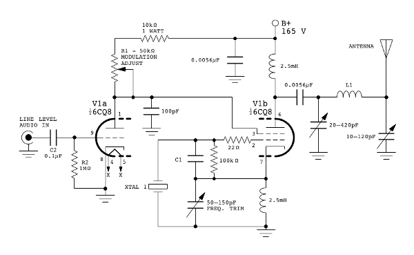
In this circuit, the tetrode section functions as a modulated crystal oscillator (Colpitts with cathode feedback), using the screen grid for modulation. Both a quartz crystal and a ceramic resonator have been used with good results. The value of C1 is 22pF when a quartz crystal is used, and 150pF when a ceramic resonator is used. Coupling from the tetrode plate to the antenna is by means of a pi-network which is adjusted for maximum power transfer. Pi-network component values depend on the transmitter frequency, and antenna length and configuration. Inductor L1, with taps ranging from about 300 to 900 micro-henries in six steps, covers the medium wave band quite well when used with a 3 meter long antenna. The following photos show top and bottom views of the constructed transmitter. (The antenna matching network and power supply are external.)


The triode section of the 6CQ8 functions as the audio pre-amp and carrier control. It uses a fixed grid bias near zero volts (with no audio input signal). There is no cathode bias. The significant point is that the combination of the grid resistor, the input DC blocking capacitor, and the diode action between grid and cathode, function as a diode clamp which clamps the positive peaks of the audio input signal to approximately ground potential. To be precise, due to grid-cathode contact potential, quiescent grid bias is about -0.5 volts, positive grid current starts to flow at about this same voltage, and so this is where the positive input peaks are clamped. As a result, the grid bias is always equal to minus half the peak to peak audio input level minus a half volt. It's important to point out, that with this circuit, the term "quiescent" does not mean "average DC level", as it often does in AC coupled circuits, where the meanings are often interchangeable; it refers to the state with no audio input signal. With varying input signal levels, the average DC levels will shift.
The following three scope traces show the voltage at the grid for no audio input, low level audio signal (300mV p-p), and high level audio input signal (2.2V p-p). The upper horizontal trace, in the first photo, indicates ground (0 volt) level.
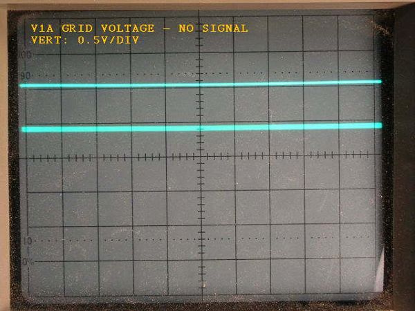
The no-signal trace shows the grid DC voltage (lower trace) to be about -0.5 volts. It drops slightly to about -0.65 volts with the 300mV input as the next photo shows.

As before, the flat trace in these two photos indicates the 0 V reference.
The DC voltage drops considerably, to about -1.4 volts with the high level input signal as shown in this photo.

Consequently, the signal at the plate will have its negative peaks near the quiescent DC plate voltage, and the positive peaks will vary with the audio signal. The average plate DC level will be proportional to the average audio level. The following two photos show the triode plate voltage corresponding to the 300mV and 2.2V inputs respectively.


In these photos, the flat horizontal trace indicates the plate quiescent voltage which is +20 volts. Again, it can be seen that as the audio signal level increases, the DC level at the plate shifts, this time in a positive direction. This average DC level on the plate is the desired carrier control. By direct coupling the triode plate to the screen grid of the tetrode, the combined audio and DC carrier control will modulate the tetrode oscillator section of the tube. A bit of research and experimentation indicates that the best type of triode for this type of application is one with a high transconductance. The triode section of the 6CQ8 has a suitably high gm of 8000 micro-siemens.
The quiescent point of the triode plate and tetrode screen is chosen to be a relatively low voltage which still allows the tetrode oscillator section to generate a modest carrier. A variable resistance is provided in the plate circuit to set this level. All deviations from the quiescent point will be in the positive direction, and accordingly, these deviations will increase the RF signal output from the tetrode.
Typically, trapezoidal oscilloscope patterns are used as an aid in setting the proper modulation levels. Unfortunately, this is somewhat unsatisfactory for a controlled carrier transmitter. In a normal AM modulator, as the audio input increases, the pattern expands along the sloped lines of the characteristic trapezoid, always maintaining a neat pattern. With a controlled carrier transmitter, a fixed level audio input will also produce a similar trapezoidal pattern. However, if the level is increased, the entire trapezoidal pattern increases not only along the trapezoidal slope, but also, the entire trapezoid expands vertically. When the input source is music or voice, rather than a fixed level signal, the trapezoidal pattern changes in size so rapidly that it's not possible to use the pattern as an exact means to set modulation levels, though it still gives some useful information. Ultimately, it's necessary to adjust for the best sounding audio at the receiver. The following trapezoidal patterns are with the transmitter at its best (experimentally found) modulation setting. The first is with a fixed 500mV p-p input signal.

Modulation is about 50% which may seem a bit low considering that the carrier level has been designed to follow the audio input level. However, while the average carrier level can increase quite rapidly, it's not instantaneous, and the 50% level for a fixed 500mV signal level allows a bit of headroom. When the input is music, the rapidly changing levels tend to give a modulation closer to 90%.
The following photo was taken with a fairly slow exposure, and shows a trapezoidal pattern just as a loud transient occurs. A double pattern is evident, showing the initial low level as a smaller trapezoid, and then the louder level as a superimposed larger trapezoid.

The next pattern is with an even larger dynamic range:

This shows another interesting characteristic of the transmitter. As the audio signal becomes very large, the modulation envelope starts to curve significantly at both ends, providing a soft limiting effect. While this hadn't been an intentional part of the design, it does provide an additional benefit, eliminating hard clipping and the unpleasant buzz which accompanies it.
One must naturally wonder what a controlled carrier signal sounds like at the receiver end. Without any AGC circuit in the receiver, the effect would be much like an audio expander circuit, which is often used in some audio systems to provide a "presence" effect. However, the AGC circuit in the receiver compensates by re-compressing the audio, reducing (but not eliminating) this effect. To eliminate the effect completely, the AGC loop gain would have to be infinite, which of course, it is not. Therefore, there remains a net expansion effect, which in my listening tests, I found to be a pleasant departure from the usual heavily compressed audio of commercial broadcast stations. I have to say that this is all subjective, of course.
It is important though, that the time constant of the carrier control, be compatible with the time constant of the receiver AGC. The carrier control time constant is set by the triode grid resistor and the input capacitor. In the present circuit the time constant is 100 milliseconds, which I found to be optimum in my tests.
Another issue to consider is the possibility of the introduction of distortion due to the triode clamp circuit. It would be expected that positive peaks of the audio signal would cause a considerable increase in grid current and therefore cause a drastic decrease in input impedance at these peaks, leading to a flattening of the top of the input signal waveform. This has proven not to be a problem. There is no visible flattening of the input signal in the above scope photos. Very fast transients would be the most probable cause of distortion. However, no distortion was audible to me during listening tests. An audio expert, with better ears than mine, might argue otherwise, but I'm quite happy with the audio quality.
One final note: While there are a number of prospective dual section tubes with the necessary high-transconductance triode section, the 6CQ8 is the only one I've found where the second section is a tetrode. I chose the tetrode because some technical literature (e.g., ARRL Handbook) indicates that screen modulation is better suited to a tetrode than a pentode, giving more linear modulation. Interestingly, various vacuum tube guides list the 6EA8, 6GH8, 6LM8 and 6U8 as substitutes for the 6CQ8, although all of them have a pentode section rather than a tetrode section. They have functionally the same basing arrangement, because the suppressors are internally tied to the cathode. So, one of these could be quickly substituted into the circuit. It may be of interest to try one of these pentode versions to compare. Unfortunately, I have none on hand at the moment. So, this will have to be an experiment for the future.
Attachments:- Transmitter Schematic Diagram (45 KB)
- Chassis Construction 1 (34 KB)
- Chassis Construction 2 (47 KB)
To thank the Author because you find the post helpful or well done.
Update
Recently, I've been doing a bit more experimenting with this circuit. In the process, I noticed an error in the schematic in my previous post. The variable resistance in the triode plate circuit shown as 50 k, is actually 1 Megohm, which is a significant difference! This error was a carryover from my previous transmitter circuit which required the lower resistance range. The earlier circuit was also a bit more touchy during setup, and I had included the variable resistance to get the best balance between carrier level and modulation. The present circuit seems a bit more robust in this respect, and I found that a fixed resistance of 820k, works well with no need for adjustment. The corrected schematic is shown below.

For the trapezoidal scope traces, I've now realized that by connecting the horizontal scope probe to the triode grid, and using DC coupling in the scope, both the audio signal and grid bias level are carried through, minimizing the double image effect. The resulting traces now resemble more traditional trapezoidal traces, making it easier to measure modulation percentages. There still remains some vertical expansion of the trapezoid, but this is noticeable only during sharp transients. Following is a new example trace.

The unmodulated carrier trace is appended to the right side of the photo. The slightly rough edges along the contour of the trapezoid are due to the remaining vertical expansion due to transients occuring during the exposure.
From this trace I made the following measurements:
Upward modulation = (7.0 - 2.2)/2.2 * 100 = 218%
Downward modulation = (2.2 - 0.2)/2.2 * 100 = 91%
The average of the upward and downward modulation is then 154%
I've made two short videos showing the dynamic trapezoid traces from two different audio sources, which show how the different levels of different program sources are handled. The audio in the clips is the actual audio received by a Sony ST-JX450A tuner. The tuner has an IF section with 8kHz bandwidth which is higher than most receivers, and therefore is less likely to mask distortion which might pass by unnoticed in a receiver with lower bandwidth. The line-out from the Sony tuner is connected directly to the camcorder line input. (Most of the background noise is due to the poor circuitry in the cheap camcorder.)
The first clip is a short excerpt from a big band tune. The second clip is a guitar tune. They come from different CDs, and there has been no adjustment in audio levels between the two. It's obvious that the big band tune has a higher average level than the guitar tune, but both give good modulation and manage to get through the transmitter and receiver relatively unscathed.
Hopefully, by providing these clips, it will allow the forum members to form their own opinions, rather than relying on my subjective comments from my previous post.
----------
Edit:
When I posted the above audio clips, there was a bit of equalization problem in my camcorder, and it was rolling off the bass below 150Hz. I've now fixed it by adding an equalization network so that the response is flat to below 60Hz, and have redone the second clip. I've also added a third clip which highlights the bass response:
Clip No. 2: African Guitar (Equalization Corrected)
Clip No. 3: Drum & Bass (Equalization Corrected)
To thank the Author because you find the post helpful or well done.
using the PCF82

I constructed the mini-transmitter with this equivalent to 6U8 with 9,5 volts filament. With a 350 microHenry coil and 3 meters antenna wire it works fine just using less than 2 milliAmperes at 150 volts HT. Input about 200 milliVolts line from a cassete-deck and a crystal of 1300 to 1600 kiloHertz. I replaced the antenna-wire by a DV27 whip (more convenient) which does the job as well. I also tested the PCF80 valve, having the same pin-out, giving less output.
To thank the Author because you find the post helpful or well done.
Substitute for 6CQ8
Good to see that it's working well for you. In an earlier post, I mentioned substitutes for the 6CQ8, and since then, I have tested the circuit with both 6U8A/ECF82 and 6GH8A, and found that the transmitter performs exactly the same with no circuit modifications. So, of course, as you have found, the equivalent PCF82 would also work exactly the same. The critical parameter is the high transconductance of the triode stage. These tubes all have a gm in the 7500 to 8000 µS range. The triode section of the PCF80 has a gm of only 5000 µS, which makes it unsuitable, as you discovered.
To thank the Author because you find the post helpful or well done.