Differential super-regenerative self-limiting FM demodulator
Differential super-regenerative self-limiting FM demodulator

Fellow Radiophiles:
The following is a translation of a section from the first book of the 3 part series "Die Röhre im UKW Empfäng" edited by Dr. Ing. Horst Rothe in 1952. This very interesting section describes a fully differential super-regenerative self-limiting FM detector. The circuit is comprised of two synchronized self-quenched FM super-regenerative detectors which are detuned from each other to achieve a symmetric S-curve characteristic.
This section came out of the chapter on super-regenerative receivers, which can be found in the original German as a pdf attachment at Der Pendelempfang für UKW
I used the Google and Bing translators to get a first translation. I edited this automated translation result and our own Dr. Dietmar Rudolph proof read the final copy. Thank you Herr Rudolph for your continuing help with translations.
Best regards,
-Joe
Rudolf Cantz
The differential super-regenerative amplifier as a self-limiting FM demodulator
A symmetrical circuit according to the “off-tune discriminator” [illustrated in figure 6-16] [13],[15] can be constructed with two super-regenerative stages in the same design. Such was first proposed in British Patent No. 571 580 (1942) [GB571580 at Espacenet], which is about the limiting effect, however, it contains an error about the operation of the limiting effect.

G. Vogt and the author of this principle have both applied this principle, in the form that both self-quenched stages are operated with the same quench frequency. Both stages are then always synchronized and are highly sensitive and at the same point in time. This keeps one super-regenerative stage from being affected by simultaneous strong oscillations in the other. The requirements for the mutual decoupling are easy to fulfill with synchronous operation, so that the circuit is feasible even with a double triode such as EDD11, when it is operated with an IF that is not too high.
It was to be expected now that such a differential super-regenerative circuit would, with an Audio push-pull output, also have a limiting effect which is similar to the well known limiting of the ratio detector. Vogt has, for example, deduced this limiter operation mathematically for the logarithmic differential Super-Regenerative circuit. In the balanced output, an interfering AM rectified current causes differential currents when the received frequency differs from the central position. This is true at least for the region that corresponds to the width of the modulation of the channel.
 Figure 20 Self-quenched Super-regenerative differential stage for a 21 MHz IF with dual triode EDD11
A differential Super-Regenerative circuit was reviewed by the author, which was designed as self-quenched with the Csp blocking capacitor shared by the two Super-Regenerative stages (Fig. 20). This could achieve a further advantage: such a differential stage works nearly logarithmically with amplitude changes, however, for frequency changes it works almost linearly. Figure 21 shows the time sweep of both grid voltages for two interconnected tubes during the growing oscillation period. The negative grid charge of the self-quenched tubes is accumulated by the sum of the grid current of the two tubes, and these probably change with signal amplitude variations, however, these currents remain constant with changes in frequency because the oscillation amplitude of a tube increases the same as the other decreases. With this differential super-regenerative circuit which was executed with a EDD11 tube for an intermediate frequency of 21 MHz, a limiter ratio over 10 could be achieved over the entire working voltage range. The limiting effect is advantageously very high even with a relatively small field strength.
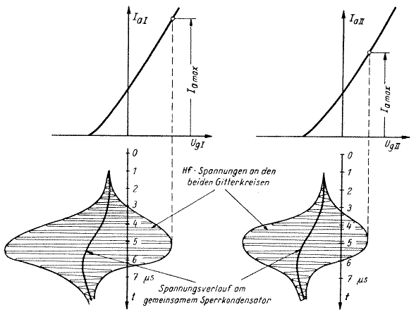
Figure 21: RF and grid voltage waveforms in the two differential stages with self-quenched Super-Regenerative circuits.
Because of the inevitable differences between the two Triodes, symmetry control is provided in the grid circuit current. This circuit is set up so that a maximum of noise is heard when the preceding stages are turned off. The alignment achieved in the whole differential super-regenerative stage uses the best portion of the discriminator curve, and the alignment is easier than that of a ratio detector. However, the grid current regulation circuit provides insufficient symmetry for double triodes with strongly dissimilar characteristics.
In the two super-regenerative valves relatively large opposing currents flow because of "Linear Operation". On the other hand, especially when using Triodes, no high external Audio output load resistors may be used, which must rather be in the order of 1kOhm. It is then possible with the least effort to connect a push-pull output transformer for wideband audio requirements without undue ripple voltage from one quench period to the next. It has been shown that the main threat to the stable operation of differential super-regenerative circuits is an oscillating term arising from low-frequency variation in the regenerative growth and decay processes for the next quench period. This can occur, for example, at a sub-harmonic of the quench frequency, and the receiver can thus become completely insensitive, or it may arise as high distortion and more or less irregular spurious tones. When tuning the receiver to an unmodulated carrier what appears is not a simple noise minimum at the center of the channel, but these strong irregular noises. In the test circuit shown in Figure 20 negative feedback resistance RG was included for the total elimination of this phenomenon.
The fundamental resonance curves of the individual quenched circuits in the self-quenched differential circuit, are relevant for linear FM demodulation. One circuit is detuned with + 150 ... 200 kHz and the other with - 150 ... 200 kHz. The usual individual Gaussian bell shaped resonance curves give a net discriminator response, as drawn individually in Figure 22. As with a conventional symmetrical discriminator, we obtain three maxima for the AF output voltage in the dashed line drawn as a function of detuning frequency delta-f. Figure 23 shows another oscilloscope photo recorded with the test circuit discriminator.
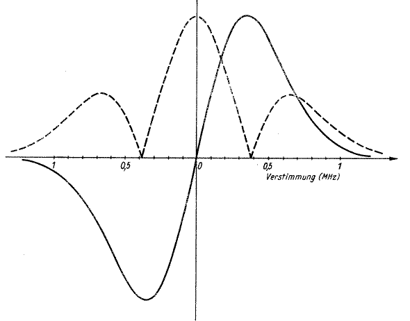
Figure 22: Discriminator and LF-voltage curve for Differential Super-Regenerative Demodulator
 Figure 23: Scope photo of Discriminator curve for the Differential Super-Regenerative Demodulator in Figure 20
The coupling of the two oppositely detuned circuits to the preceding stage, which may be a mixing stage, takes place via two capacitors, which must not be too large so that the two circuits oscillate sufficiently independently of one another. Using a double-triode for the two quenched stages brings added parasitic coupling via the internal capacitances between the two Triodes, which can then be counteracted with the application of a neutralizing capacity. Ultimately, it is still possible to satisfy the decoupling conditions with the EDD11 tube at a 21MHz intermediate frequency.
When operating the differential super-regenerative stage directly at ultra-short-waves, then two completely separate Triodes are used.
[1] Cantz, R.: Der Pendelempfang, in Rothe, H. (editor): ”Die Telefunken–Röhre im UKW–Empfänger“, Franzis, 1952
[13] Compare to the symmetric detector circuit description in ”FM-Demodulatoren“, S. 23. in [1]
[15] Ghirardi, A.A.: Receiver Circuitry and Operation, Rinehart, 1955
To thank the Author because you find the post helpful or well done.