EF50 (EF50)
EF50 (EF50)


|
The VALVE development continues rapidly and concerns both the characteristics and method of construction. A new Mullard type of valve of exceedingly unorthodox construction is described in this article. |
 development of the technique of radio valve manufacture was assisted in the early stages by the experience gained in the product ion of incandescent lamps. Although originally developed for the lamp, the glass bulb and foot, with its pinch, were adopted for the vacuum-tight envelope of the valve. Recent receiver development, however, has raised Problems which are difficult of solution with the existing valve technique. This is especially so in the case of short-wave and television apparatus.
THE
Some of the difficulties encountered in the original method of construction is developed from incandescent-lamp manufacture, can be summarised as follows:
(1) In certain valves of the old construction it was found necessary to connect anode and control grid to the opposite ends of the valve, which sometimes complicates receiver design.
(2) Long internal connections from the electrodes to the external contacts considerably increase the actual capacities and inductances of the electrodes. This gives rise to serious difficulties when dealing with short waves.
(3) Long connecting leads from the electrodes to the contacts also cause appreciable Variation in the effective inter-electrode capacities. This effect is made worse by the presence of the "getter" deposit in the neighborhood of the pinch.
(4) The Bakelite used in the manufacture of the base of the valve is rather unsatisfactory, partly because its dielectric constant varies with temperature, and this causes some change in the effective valve capacities during the warming-up period after switching on.
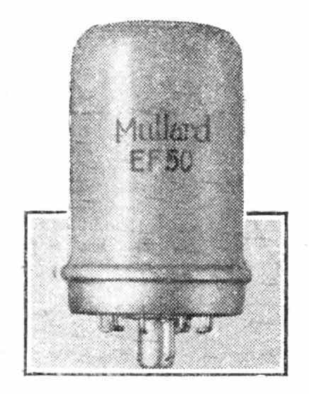
In an attempt to solve these problems the Mullard "All-glass" valves have been introduced, and in most respects they prove to be a satisfactory solution, readily adaptable to mass production. The photograph shows the external appearance of one of these valves, the EF50, and Fig. 1 shows the constructional details.
The Bakelite base and the foot with its usual pinch have been eliminated and replaced by a machine-made pressed-glass base (A). This glass base includes the chrome-iron leading-out wires. Chrome-iron is chosen for this purpose because it has a coefficient of expansion similar to that of certain qualities of glass, and in other respects it proves to be very suitable for making vacuum-tight seals.

The seal between the bulb (B) and the glass base forms the flange (C). The "getter" deposit (D) is located exclusively at the top of the bulb. The exhaust tube (E) is part of the glass base, and both the exhaust tube and the base are covered with a metal screen (F), which is provided partly to give mechanical protection of the exhaust tube and partly to allow of external electrical screening between the control grid contact (G1) and the anode and heater contacts.
The provision of a locating spigot (H) facilitates the correct insertion of the valve into the socket. This is similar to the method employed in the octal base.
The External Contacts
When inserted in the specially designed socket the silver-plated chrome-iron contacts at the base of the valve have a contact resistance of 5 to 8 milliohms, which compares favorably with other existing bases.
This method of making the connections has the advantages that there are no soldered joints on the valve, and there is no base which can become loose. More important, the connections between each electrode and the point where the external circuit wiring is soldered to the contact springs on the valve holder are very short.
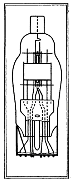
Fig. 2.—The greater length of the internal leads is clearly shown in this drawing of an ordinary valve.
The Internal Leads
The arrangement of the leading-out wires in a typical small valve, the EF9, with a pinch construction is shown in Fig. 2. The wires run more or less parallel with each other inside the foot for a length of approximately 35 mm, compared with 15 mm in the all-glass construction.
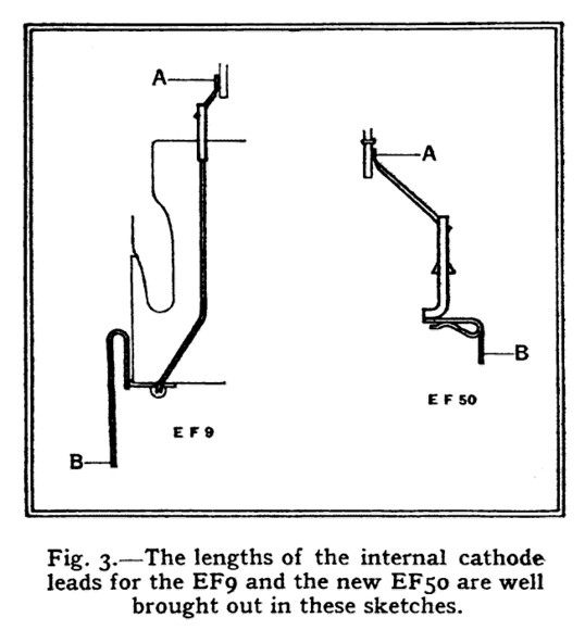
In Fig. 3 the total length of the connection from the cathode A to the cathode contact soldering tag B on the valve holder is compared for the EF9 and EF50. This length is of importance in short-wave work, particularly at the wavelengths used for television, and the diagram shows that it can be reduced from 65 mm to 45 mm, a decrease of more than 35 per cent.
Further advantages are obtained by the elimination of the Bakelite base, since Bakelite has comparatively high-dielectric losses and a dielectric constant, which varies, to some extent with temperature change. As a result of this and other causes the capacity variations of valves during the warming-up period give rise to considerable frequency drift eliminating the Bakelite base assists appreciably in the improvement of this defect. The effect described is well brought out by the figures of Table 1. These measurements were made at a frequency of 15 Mc/s and an ambient temperature of 25° C.
|
TABLE 1: frequency drift |
||
|
Valve type |
Time after which 80 % of the total drift is reached |
Total drift |
|
EK2 - Bakelite base. |
12 minutes |
4.4 kc/s |
|
EF50 - all-glass |
9.5 minutes |
2.7 kc/s |
|
ECH11 - all-metal valve with bakelite base. |
11.8 minutes |
5.5 kc/s. |
As shown in Fig. 1, the control grid connection of the EF50 has been taken to the base. In the pinch construction this would not be permissible, because it would give rise to insufficient screening between the control grid and the anode and heater. The external screen (F) and the internal screen ensure very small anode-to-grid and heater-to-grid capacities in the EF50. The anode-grid capacity is less than 0.002 mmfds, and the grid-heater capacity is less than 0.003 mmfds.
These values, which include the capacities of the socket, are quite as small as those measured on the EF9 with the control grid lead taken out to the top cap.
It has been found in practice that the input and output capacity tolerance at the EF9 cannot be reduced below ± 0.6 mmfds, the input capacity being 5.0 ± 0.6 mmfds, and the Output capacity 7.0 ± 0.6 mmfds. On the other hand, the all-glass type EF5O can be made with input and output capacity tolerances of only ± 0.2 mmfds. In some applications this is an important advantage.
It is possible to work to these reduced tolerances because the lead-out wires in the pressed-glass base are always the same distance from each other, and these distances are greater than in the normal pinch construction. Further, the "getter" deposit is at the top of the bulb and no longer influences the capacities between leads, and the mechanical stability of the electrode System is greater in the new construction.
An additional advantage of limiting the "getter" deposit to the top of the bulb is the reduced risk of bad insulation between the support wires, thus obviating the necessity for the well-known white insulation material on the pinch, which can give rise to crackling noises.

In the conventional pinch construction all lead-out and supporting wires in the pinch are in one plane. This necessitates the well-known dome mica construction. In the all-glass valves the supporting wires are arranged in a circle (see Fig. 4). This increases the mechanical stability of the system to such an extent that the additional support of the dome mica construction is not required.
The dimensions are of the same order as those of other types of small valves as shown in Table 2.
|
TABLE 2 |
|
|
|
|
|
Valve types |
||
|
|
EF9 |
EF50 |
EF11 |
|
Length in mm |
86 |
60 |
55 |
|
Diameter in mm |
30 |
32.5 |
42.5 |
|
Weight in grams |
24 |
28 |
46 |
A point of special importance to set-makers 's the possibility of transporting sets with the valves in position without risk of the valves shaking out. With this object in view the socket for the all-glass valve has been designed on the bayonet-lock principle. This has the advantage that the valve can be firmly secured in its socket by applying comparatively light pressure, followed by a twist, after which the valve cannot be removed unless a twist is applied in the opposite direction.
This socket has proved entirely satisfactory for use in apparatus designed for aircraft.
Thanks to Jeremy Harmer for contributing this article to radiomuseum.org
Für diesen Post bedanken, weil hilfreich und/oder fachlich fundiert.