FM Only Kit using CXA1619
FM Only Kit using CXA1619
A kit is available from Sri Lanka on eBay at a reasonable price. It includes the 10.7 MHz ceramic IF and discrimator parts as well as pre-wound VHF colils. The kit may be powered from 5V USB, 4 x AA cells etc and only needs aerial and loudspeaker to operate as the AM/FM IC has the mono audio amp built in.
The kit has no schematic, however the design seems to be similar to the datasheet, but with AM mode unused. I'll examine the PCB to see if AM can easily be added as the tuning capacitor has the AM gangs and copper pads for them.
Sony no longer makes these, but NOS is available from $3 to $8 approximately. It was intended for walkman cassette players with radio.
There are cheaper kits, on eBay, with a case that use TDA7088 / CD7088 type part (surface mount soldering!) for FM and TA7642 TRF IC (TO92 package, like ZN414 or MK484) for MW AM, that works surprisingly well 76MHz to 108MHz and 550KHz to 1.7MHz using 2 x AA cells.
To thank the Author because you find the post helpful or well done.
The FM only CXA1619BS kit form Sri Lanka
Kit PCB CXA1619BS FM Only
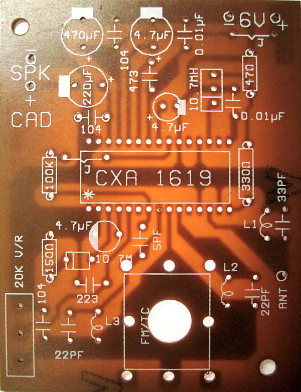
Image below is annotated by me to match application note #2 in Sony datasheet.
! means part missing.
* Means value changed.
An extra 47 Ohms is added across CF2, the 10.7MHz IF filter.
Two parts are not as the overlay: A 10uF is supplied instead of a 4.7uF, but that is correct beside the 470uF, the largest circle for a 4.7uF.
The Audio couping is 0.47uF on application note, and 1uF on some example circuits. A 0.047uF (47nF) is on overlay and supplied. I'd be inclinded to use 0.22uF to 1uF instead.
The AFC -AGC decoupling capacitor pin 22 is missing.
Vreg is decoupled with a 100nF (0.1uF) rather than 10uF and 10nF in parallel.
The Volume control reduced from 50K to 20K and R2 (10K) replaced with short circuit.
 It looks like AM could be added.
I may try open circuit C2 and C3 with route FM IF filter to AM detector to see does AirBand (110MHz to 137MHz) work at all. Parts as received:

To thank the Author because you find the post helpful or well done.
Building kit: Airband vs FM Band II
I assembled the kit and found that the volume control has reverse action.
Here is what I think the circuit of the kit is (edited from Sony Data):
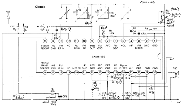
The kit has a parts list and some instructions (two sides of an A4 page), but no schematic circuit. Values in brackets are on the Sony Datasheet, I later changed to them, see below.
C7 seems high at 5pF, which would explain why the LO trimmer is at a much lower value position than RF trimmer. Perhaps this is why C2 has been increased from 18pF to 22pf (I changed it to 18pF).
It works well off 3 x used AA cells (about 4.3V or less). It certainly works no better or louder at 6V. A 5V USB supply, 4 x cells, a single LiPoly (with protection circuit included) or even 2 x AAA cells should work.
Speaker volume is low as the IC only intended to drive an earphone. Note that there is no loudspeaker or tuning knob included. The brass boss for the tuner is larger than the regular size. The two PCB mount screws are also not included.
The coils have same turns as the Sony Application note / Datasheet, but are internal diameter about 2.5mm. The specification is 4mm internal diameter. The lowest frequency received was actually 107MHz, the radio did pick up local Shanwick and Shannon ATC on AM Airband, with the FM detector.
I wound new coils with roughly 0.6mm wire (recommended) and 4mm internal diameter and then the Band II 87MHz to 108MHz was easily tuned.
I added 10uF at pin AFC/AGC pin 22 at the 100K resistor. I increased 473 (0.047uF) to 0.47 electrolytic as per datasheet (474) C15. I removed 47 ohms on input to ceramic filter, which would reduce IF to about 1/8th? I replaced 20K pot with 50K pot in series with 10K as per data sheet and put the 0.022uF capacitor from there on the 0.01uF location, C16, probably de-emphasis. I increased L1 from 5t @ 2.5mm core to 7t @ 4mm core.
The radio works well now on Band II FM, but needs an additional amplifier to drive a speaker. Next I will try adding AM (perhaps, LW, MW & SW) and examine the metering. Then I may try it with a TDA7040T stereo decoder.
Really I think the CF210SP kit using TDA7088/CD9088 and TRF for AM is better value, though it has one SMD part to solder. I will explain how that is actually easy! However, perhaps this kit has more potential to experiment with Superhet operation and multiple bands. I will experiment with diode switching of the C2, C3, L2, L3 for Air Band and also shortwave dual conversion using a NE612 /SA612 to convert from 10.7MHz to 455kHz. One experiment is to see if the VHF LO and RF amp and mixer are still active in AM mode!
I will try reduction of 5pF to 1pF or 2pf at pin 8 to 7. The AFC action is noticable, as it stays on station with a wiggle of tuning once it's tuned.
To thank the Author because you find the post helpful or well done.