freixa: Periquito operation, repair and alignment
freixa: Periquito operation, repair and alignment

Fellow Radiophiles,
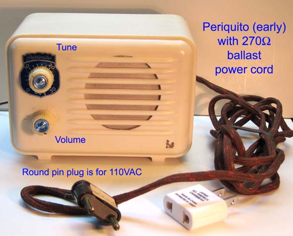
Recently, I got a very small model Periquito by Catalan radio maker Luis Freixa. My version is the early one with the ballast resistor for the series heater string in the power cord. later versions used an internal ballast resistor. I will share here what I learned from tracing it's circuit, repairing and aligning it.
Circuit operation
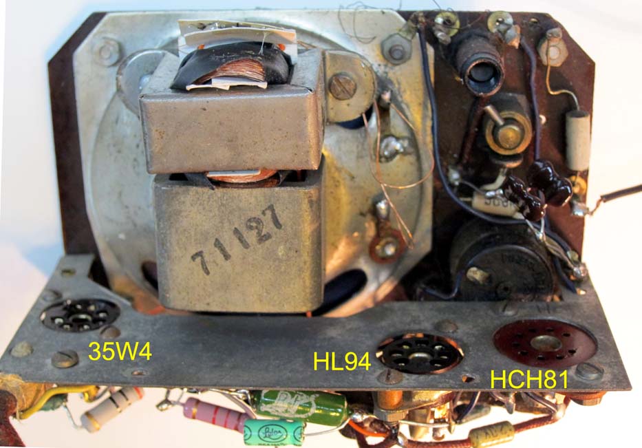
This radio has a unique 3-tube design with the HCH81 HL94 35W4 heaters wired in series with an external 270Ω power cord ballast to drop the external 110VAC to 77VAC at 150mA. One side of the power cord is wired to the chassis, which also serves as the ground system for the wire antenna. When operating this radio with an isolation transformer on the repair bench, it is necessary to ground the chassis for good reception. When plugged directly into 110VAC outlet, one plug-in orientation gives less hum. But do not ground the chassis if the radio is plugged directly into the mains.
After the radio is back in it's case keep in mind that the two holding screws under the case are electrically connected to the chassis and are therefor connected to one side of the power line. When the power switch is on, the chassis is directly connected to one side of the power plub. When the power switch is off, the chassis is tied to the other plug terminal via the the tube heaters. So, it is best to keep this radio over an insulated surface. I perfer this approach to rewiring the radio with a polarized plub, that has the neutral always tied to the chassis.
The power cord barely warms up while dissipating 6.5W, but it is still necessary to keep the power cord uncoiled to prevent it from overheating. The power cord ballast is in very good shape and it is made very differently from American ballast cords of the 1930's. The cord in the Periquito is entirely made of plastic materials, which have kept their resilience, while most of the 1930's ballast cords were usually made with rubber and asbestos. The rubber in these older cords usually hardens up, which tends to make the NiCr resistance wire break when the cord is flexed.
The 35W4 rectifier and it's circuit are common enough.
The HL94/30A5 audio power pentode is somewhat unusual. With it's 30V heater, It dissipates less power than the 35V or 50V 150mA series heater alternatives. However, the HL94/30A5 has 9.2mS of transconductance, which is noticeably higher that of the common 35C5 with only 5.8mS. If the 30A5 is hard to find, a good substitute is the 35EH5 with gm=12mS, but this may require reducing the cathode bias resistor from 150Ω to 62Ω. The 35EH5 may actually be an improvement over the 30A5 with it's higher gain and lower plate current. Every bit of gain counts in a 3 tube radio.
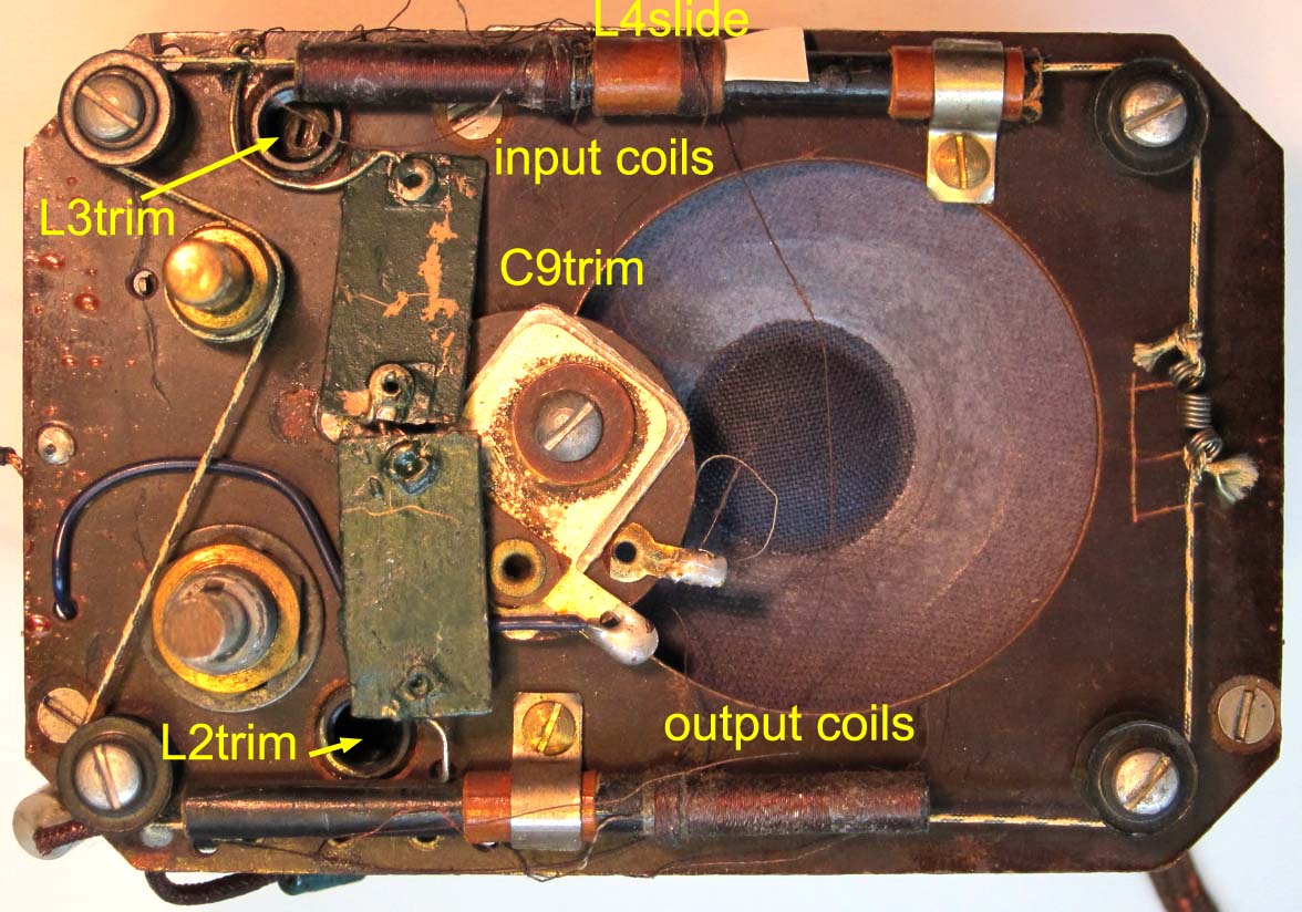
The front end is where this radio's design is unique. It uses the HCH81 Heptode/triode tube, but not in its usual frequency mixer and oscillator configuration. The heptode is wired in a reflex configuration as RF and AF amplifier, while the triode is wired as a simple diode detector. The input and output of the Rf stage have two permeability tuned circuits that are tuned together with movable slugs attached to the dial cord. The RF circuitry also employs inductively coupled regeneration with L4-slide from the tuned plate circuit to the tuned grid circuit to increase gain and selectivity in the single RF stage.
The detector low pass filter C9-Trim is adjustable and serves to control the regenerative feedback at lower frequencies. I was not able to determine conclusevely the phase relationship between the primary and secondary of the two RF transformers. This feedback is also mediated by the diode detector at the triode plate, so it could be said that a form of regenerative detection is present.
It is surprising to see the triode employed as a simple diode detector, as opposed to a grid leak detector configuration that would yield higher gain. However, this would have necessitated moving the gain control to the antenna circuit to avoid detector saturation on strong stations.
One curious coincidence is that the HCH81 heptode/triode and the EBF89 pentode/dual-diode pinouts are compatible in this design. However, the EBF89 heater requires 6.3V/300mA. The EBF89 would have given higher gain with it's gm=4.5mS; while the HCH81 has gm=2.4mS. I am not aware of a 12.6V/150ma heater version of the EBF89.
Note that there is no RF filter capacitor at R7 to block RF energy from the audio power pentode. the only RF filter is C5-black at the HL94 audio power pentode plate. The C5-black capacitor also serves to protect the plate circuit from high voltage spikes that would occur without a plate capacitor when the plate current is suddenly cutoff with a noise spike.
Some incidental RF filtering will also happen as the high impedance of the volume control is loaded by the input capacitance of the power pentode. This effect must be significant because the regenerative oscillations are more likely to occur with the volume control at full volume. Even backing off the volume control by about 10% of it's range is enough to kill the oscillation. When the regenerative feedack coil L4-slide is not coupled to tightly, there are no oscillations at any volume setting.
Repair
The power switch was dirty and measured 50Ω, so I cleaned it with DeOxit, and it is fine now.
The original HL94 tube was weak, so I replaced it with a 30A5 equivalent. The electrolytic caps had already been replaced and I checked the other caps for leakage.
![]()
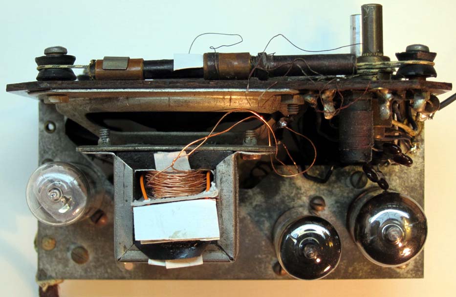
![]() The only serious repair problem was the burned out primary of the audio transformer. I thought of rewinding it, but that would be too many turns of fine wire without a mechanized winding setup. I resorted, instead, to a transformer transfusion. I took the primary winding of good small 120V/12V transformer in my junk box and placed it over the core of the original transformer with a card insulator over the iron core. Then I hand wound the secondary with heavier wire. The card insulators and electrical tape insure that the enameled windings never touch the core. I counted the turns on the primary with the goal to get a 27x turns ratio. The primary turns were never counted. The number you see is an estimate from the voltage/turns ratio and the known secondary turn count.
The only serious repair problem was the burned out primary of the audio transformer. I thought of rewinding it, but that would be too many turns of fine wire without a mechanized winding setup. I resorted, instead, to a transformer transfusion. I took the primary winding of good small 120V/12V transformer in my junk box and placed it over the core of the original transformer with a card insulator over the iron core. Then I hand wound the secondary with heavier wire. The card insulators and electrical tape insure that the enameled windings never touch the core. I counted the turns on the primary with the goal to get a 27x turns ratio. The primary turns were never counted. The number you see is an estimate from the voltage/turns ratio and the known secondary turn count.
![]()
![]()
![]()
 The only other significant repair was the creation of a missing screw in the one of the knobs.
I used a small carbide-fiber cutting wheel on my high speed hobby drill to cut two grooves at the end of a a 1" long 4-40 screw. This screw was used to tap the screw hole which had been worn smooth.
Then I cut away the sides of the the head of a short 4-40 screw and cut it's length to find the knob without protruding. The original slot remains on the screw.
The other knob is functional but has some of it's plastic broken away and I have not yet attempted this kind of reconstruction repair.
Alignment
Perhaps the strangest thing in this radio is that the case markings for the tuning and volume knobs are reversed. The volume is adjustable from 14 to 5.5, while the tuning is from 0 to 30. Perhaps the case was designed well in advance of the chassis.
All the alignment adjustments in this radio, except for C9trim, are inductor adjustments. I found no alignment instructions for this radio, so I improvised.
This alignment sequence emerged from the experimentation:
0-If the radio is oscillating, move the positive feedback coil L4slide to the right to reduce it's coupling until all oscillations stop anywhere across the band.
1-Tune the low end of the band at 550kHz to get the iron slugs on the dial cord all the way into their coils.
2-Loosen the two small metal clamps that hold the coils in place and gently nudge the input and output coils along the top and bottom of the front panel to the left or right for peak signal output with a 550kHz input.
3-Move the tuning knob to the high end of the band at 1600kHz and apply a 1600kHz signal. Adjust the two small coils L2trim and L3 trim for peak output.
You may have to repeat and experiment with steps 1-3 to get good alignment across the band. After you have aligned with 550kHz and 1600kHz, you may want to touch up the aligment with two frequencies that are a little further from the end, like 650kHz and 1400kHz.
4-Now what is left is the RF regeneration adjustment. Two adjustments control regeneration. One is L4slide at the top coil and the other is the mica capacitor at the center of the front panel. The function of L4 is obvious: just move it left towards the other coils on the same form just before oscillations occur. Check for oscillations over the entire band.
5-The purpose of C9trim is less obvious, but it appears to also control regeneration. The inductive feedback from step 4 should favor the high end of the band, while the feedback path via C9trim should favor the low end of the band. I found that I had to add 300pF in parallel with this cap to obtain stability. This adjustment is less critical than step 4.
After all adjustments are complete, the two little metal clamps should be tightened. I also found it necessary to slip a small piece of card stock under the sliding coil L4slide to keep it stationary.
Prof. Rudolph has recently posted a very useful guide on how to drive a wire antenna input with an RF generator. I read the German language post with the Google translator. This is particularly relevant for radios like this one, that have no built-in loop antenna.
A few photos

Regards,
-Joe
To thank the Author because you find the post helpful or well done.
EBF89, HCH81

Hello Joe,
in answering your question about a 12.6V/150ma heater version of the EBF89: there is no evidence of such a tube, which my have been called HBF89 then, if it ever were produced.
However, for the predecessor of the EBF89, the EBF80 from 1949/50, there is even a 12.6V/150ma heater version, called 12N8.
Amazingly, this tube was only in the French market and was only sold under its American-style designation 12N8, it would have been the "HBF80" in the European tube designation system, just as was the 6N8 the EBF80. However, the EBF80- family has less gain with a gm = 2.2 mS only.
They way the HCH81 triode is wired as a signal diode is rather unskilled in my opinion, by connecting the grid to cathode and using the triode plate as diode plate, as this increases the internal voltage drop undesirably.
If a triode is used as signal diode, one can tie grid and plate together as diode plate, or one can use the grid solely as diode plate and using the triode plate as shield by wiring it to ground.
Best Regards, Jacob
To thank the Author because you find the post helpful or well done.
Detector sweeps
Hello Jacob,
Thanks for the clarification on the possible EBF89 variations. I suppose, I will keep the HCH81 as is.
You brought up very interesting considerations about the detector that had not occurred to me.
As is often the case, this makes me do some curve tracing. This time, to find out what is going on with the plate and grid I/V characteristics for the triode.
 Your suspicion that the plate detector has a larger drop is correct, as can be seen in the curve labeled "Grounded grid Swept plate". In this case, the relevant characteristic is the low slope of the trace to the right of point 1.
This is a clear disadvantage for large signal detection for 0.5Vp-p or more.
For a little radio like this with relatively little gain before the detector, it becomes important to consider the detection efficiency below 0.5Vp-p, which represents a span of 5 horizontal divisions.
I have found in the past that small signal detection by vacuum tube diodes is more difficult to assess because of the built-in potential provided by the space charge and the necessity to load the diode with a tank circuit impedance that is similar to it's own impedance.
The loading after the RF ripple filter capacitor sets the bias level for the diode. In this case, this load is 560kΩ, which is represented by the yellow line at the bottom, and the conductance of the Heptode grid, which is represented by the right-most green trace in the plot.
The two central green traces represent using the grid with a grounded plate, or using the plate with a grounded grid. At the intersection point 1, they work similarly, but with swings above 400mV p-p, using the grid is better, as you point out.
The left most curve is for your first suggestion, which is to tie the grid and plate together. This offers a clear advantage over the other two configurations, because the curvature at the load line intersection point 2 is sharpest thus promising the most sensitive detection, as you suggested.
I included the additional trace on the far right to show what DC loading effect the control grid of the heptode might have on the detector. The Heptode control grid current is fairly significant when using just the plate or just the grid for detection at the central traces. But is much less significant when the grid and plate are used together at the left-most trace.
The effect of the Heptode negative grid current at point 1 is to cancel some of the bias current provided by the 560k load resistor, thus moving the effective location of point 1 to the left, where the curve is flatter and detection is less effective.
This is one more reason to take your suggestion to use grid and plate together as the detector. This configuration offers the steepest curvature at the load line intersection point 2, and is less effected by bias loss by the Heptode grid.
See Philco 80b detector bias with a similar analysis for grid leak detection.
I changed the detector configuration to use the grid and plate in parallel, and this gave a very clear improvement in sensitivity for strong and weak stations.
When I changed configurations from plate detection with grounded grid, to plate+grid, the RF signal at the plate dropped by about half, while the audio output increased very audibly.
Thanks for the suggestion, Jacob. It worked great!
Regards,
-Joe
To thank the Author because you find the post helpful or well done.
HCH81 heptode unit
Hello Joe,
I'm pleased about my tip was of positive value. I'm sure this was not the first disadvantageous design in a radio receiver. In some cases there were much bigger mistakes like this one.
Since the heptode unit of the HCH81 is used as RF and AF amplifier in reflex configuration, this will give opportunity for experimenting, for example by separating the RF and AF amplification by using G1 as control input for RF only and G3 for AF only – or vice-versa.
Here I think about those ingenious tricks you applied at the HI-FI AM transmitter circuits.
Perhaps one can combine RF and AF amplification similar as oscillator and G3 modulation at your transmitter ?
Best Regards, Jacob
To thank the Author because you find the post helpful or well done.