German Multi-Cavity Magnetrons
German Multi-Cavity Magnetrons

Very few is known today on the developments of multi-cavity magnetrons in Germany during the war. Available sources just refer to LMS10 which is the accurate copy of the British CV64. It was made by Telefunken in 1943, after the capture of an H2S radar set near Rotterdam. We will see that soon later German industry developed its own line of power magnetron tubes which considerably departed from that used by Allies. They were ready too late for significant operational uses, if any. Anyway their productions were so small, often limited to a few experimental or pre-production samples, to the point that their very existence was doubtful until today.
Historical backgrounds
The use of magnetron tubes for radio-localization transmitters started quite early in Germany as in other countries. In 1934 GEMA was experimenting 50 cm systems based upon split-anode magnetron in the transmitter section. Any kind of known magnetron structure was investigated in the thirties both by industries and universities, among which water-cooled split-anode types, similar to the 5J29 manufactured years later by General Electric and used to jam German radars. Starting from the basic split-anode magnetron design, the German industry developed many interdigital types for frequencies from 300 MHz up to about 5 GHz and for output power up to a few tens of watts. A couple of them are in the images below.
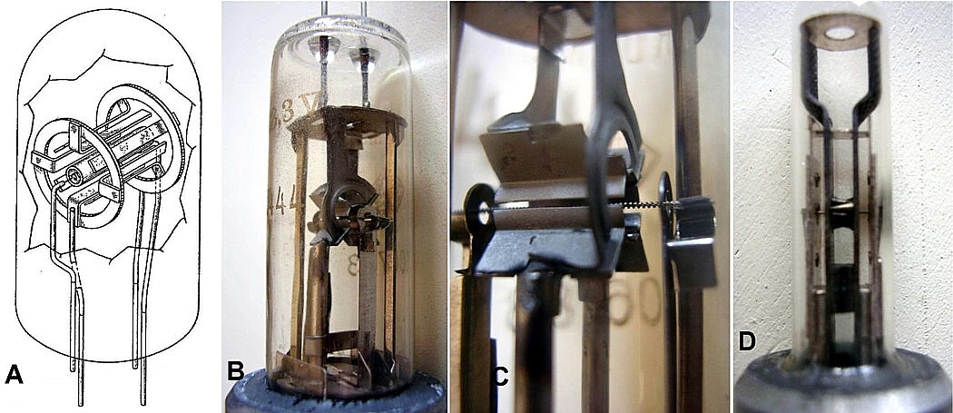
Fig. 1 - Multi-segment or interdigital magnetrons can be seen as evolutions of the split-anode type. Segment pairs are connected to the two wires of a Lecher line resonator. A) Draft of a typical eight-segment interdigital magnetron. B) RD4Ma was a four segment magnetron designed to operate from 1.1 to 1.6 GHz, delivering about 15 W CW. C) Close-up view of the four segments surrounding the filamentary cathode. D) RD2Mh could deliver 300 mW CW from 4.3 to 5.5 GHz. It was capacitively coupled to the external resonator. A similar device, the RD2Md, was used as local oscillator in the receiver of the Berlin microwave set. Click on image to enlarge.
RM 4025 - 3-cm split-anode, internal resonator magnetron
Although very late, the RM4025 reveals another kind of split-anode design, similar to the one described by G. R. Kilgore of RCA in 1936. In this structure the resonating system is self-contained, to keep losses as low as possible. The RM4025 was designed by Siemens & Halske, being in a quasi-experimental phase at the end of the war. The sample in the photo below looks unused, with an US War department label that indicates in 1946 the date when it was classified.
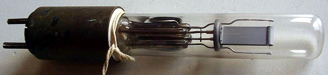
Fig. 2 - Siemens RM4025 looks to be a split-anode, self-contained resonating system magnetron. It was designed for operation at 3 cm. Still in evaluation phase at the end of the war. Click on image for full available information.
The purpose of this magnetron is hard to guess. Likely the bulb is hard glass, with long X-shaped press which supports the tiny filament and the self-contained resonating system. Its overall dimensions and the size of the internal system are typical of low-power CW devices. On the contrary, the few data available, 2 kV and 4 A max anode ratings, talk of power levels not compatible with its apparent heat dissipation capabilities. We can only think it was designed either for high-duty pulsed mode or for CW mode, with power limited to a reddish coloration of the anode. The resonant frequency of its internal system is fixed, excluding any reasonable use in many kind of applications, jammers or local oscillator in microwave receivers. Likely it was intended for a kind of active guidance system or for pulse modulated telemetry, designed to operate full power only for a short while. Unfortunately these are just conjectures, since no info can be found even on the dates in which this device was designed.
The above overview clearly shows that Germany was one of the leading countries in the research on magnetron tubes even before the war. A variety of low-power CW magnetrons was developed in the years, used as RF sources equivalent to the American or British reflex klystrons. After the early experiments on their use in radio-detection, VHF and UHF transmitting triodes were eventually preferred, due to the poor frequency stability of split-anode generators and even to more reliable target detection at somewhat lower frequencies. From 1936 onwards, Germany concentrated its efforts upon sets operating approximately from 100 to 600 MHz, at the same time abandoning any further research on higher frequencies power sources, as British did.
The multi-cavity power magnetron
From early successfully experiments in February 1940, British did their best to keep secret the multi-cavity magnetron. When the early H2S aircraft sets were ready, no authority for flying magnetron fitted radars over enemy lands was given, fearing that the secret could fall in wrong hands. Around the end of 1941 a variant of H2S, based upon the power klystron CV150, was approved for political, rather than for technical reasons: the capture of a radar set using klystron transmitter would have deceived the enemy, giving information on the state of art in England at the beginning of 1940. The contract for supplying 50 modified H2S went to EMI Hayes and its design was in charge of a group leaded by the television pioneer A. D. Blumlein. Unfortunately, while the entire EMI team was running comparative tests between their prototype and a magnetron equipped H2S, the V9977 Halifax aircraft where the second system was installed crashed, killing the entire EMI design team. On 15 July 1942 the contract was canceled and thereafter the magnetron version of H2S was authorized to fly over Continental Europe.
Germans learned of the British magnetron in February 1943, when a Stirling bomber, equipped with the 10-cm H2S radar S/N 6, was shot down near Rotterdam. They soon started copying the entire system, including the CV64 strapped magnetron. Time was spent to adapt the British design to their different technologies, a necessary step due to shortage of strategic materials, as the cobalt used by Allies in their permanent magnets. As result, some details were changed in the Rotterdam copies and the few sets built were actually completed with permanent magnets from other crashed or captured planes. By May 1943 at least four LMS 10, the Telefunken copy of CV64, had been delivered. Anyway, even due to the supply difficulties for many parts, the production of Rotterdam sets was limited to few units.
The early experimentation was soon followed by a design review based upon parts easily attainable with German technologies. In the Berlin FuG224 the big magnet was replaced by an electro-magnet driven by a controlled current and the klystron in the receiver was replaced by a small CW magnetron, the RD2Md or the RD2Md2. By early 1944 Berlin A of entirely German design, was ready for production. But, after the invasion of Normandy, the war was at the door. German industry was suffering accurate bombardments, mostly directed by X-band Allied radars. The major manufacturer of LMS 10, Sanitas, was destroyed and the same Telefunken plant at Schulze-Wechsungen was damaged by air bombings. Telefunken average production of LMS 10 was very low, around five units per month. At the end of the war, few hundreds Berlin 10-cm sets had been built, with an estimated production of LMS 10 under a thousand units.
LMS 10, the only German multi-cavity pulse magnetron really known until today, was just a copy of the British CV64. Samples of other German magnetrons recently found reveal the state of art reached in that country before the end of war. The samples were captured by American troops and stored somewhere for a long while. They came back to light in 2018, still with their US War Department identification tags dated 1946, after more than seventy years.
Very few is known of the 3-cm German magnetron. In January 1944 Germany learned of its use, after the capture of an American X-band set from a crashed plane near Meddo, a small village in Holland. We do not know whether the magnetron in their hands was the 2J21, used in the early APS-4 sets, or the strapped 725A already released at the date. This time Telefunken took the decision to build new magnetrons to its own design. LMS 12 was the first type of a family of cylindrical devices. Early samples of this X-band magnetron were delivered around August 1944. At first glance its shape could suggest that it was intended to be operated in the magnetic field generated by a coil surrounding its body. Actually we know that the 18-resonator system was implemented transversely to the axis of the tube, as in the image below.

Fig. 3 - Left, the internal construction of the new family of German magnetrons. Right, hypothetic shape of the tapered electromagnet polepieces.
Cathode and anode were preassembled on a ceramic support before inserting them into the upper sleeve. The sleeve was then brazed on the anode block. German design did not require the gold seal used in the early British magnetrons. No cooling radiator was provided, heat being transferred by conduction to a radiator in the external mount. Also optimized was the mass of magnet polepieces, tapered to concentrate the magnetic flux in the region between cathode and anode.
LMS 12 was used in a few tens of the 3-cm Berlin-D and in some experimental ancillary upgrades for other UHF sets.
Telefunken also designed scaled-down versions. One of them was the LMS 13, operating at 18.5 GHz. It never went into production and therefore did not reach any operational use.
The samples of LMS 12 and LMS 13 German magnetrons are so rare as to be considered the only ones existing today.
LMS 12 - Telefunken 3-cm multicavity magnetron.
Not known the influence of the captured Meddo set on the decision of designing it. Certainly it radically departs from the designs of LMS 10, exact copy of the British 10-cm CV64, and of any other magnetron used by Allies. The resonating system of LMS 12 embodies 18 cavities, while British and American X-band magnetrons were 12-cavity designs. Likely the decision of using the 18-cavity resonating system was taken to operate in a relatively low magnetic field. Its shape vaguely resembles a British micropup triode. The magnetic field was probably generated by an electromagnet, since we know that the cobalt needed for strong magnets was unobtainable in Germany at the time.
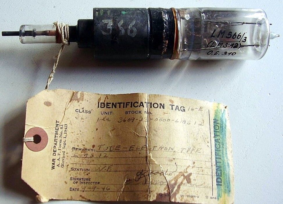
Fig. 4 - This sample of LMS 12 looks unused. On the glass bulb the Telefunken experimental coding as LM 566/3 is well visible. It still retains its US War Department classification tag, dated 1946. The rod on the left looks to be the center conductor of the coaxial output. The two heater/cathode pins are on the right of the large glass bulb. Click on the image to enlarge.
Looking at the few summary data available on this device, we note that its efficiency was quite low, just over 5%. This could derive from spurious resonating modes caused by the high number of resonators. We know that the first 3-cm magnetron developed at MIT in the summer of 1941 had 18 resonators. It gave 5 kW peak power but Fisk in his article on the BSTJ, April 1946 reports ‘the design suffered from a confusion of many modes in the resonator system...’.
Basing upon the few data available on the production of Berlin D sets and on the average production capability of Telefunken for other magnetron types, we can assume that less than 100 units were manufactured before the end of the war. Today this sample, preserved in perfect shape, is believed to be the only one still surviving.
LMS 13 - Telefunken 1.5-cm multicavity magnetron.
No doubt that LMS 13 is one of the rarest and most fascinating witness of the progress made in a few months by Germans in the microwaves. It looks to be a scaled-down variant of LMS 12, rated for 5 kW peak at 18 GHz. Similar shape and similar internal resonating system but smaller in size. It was first announced at the end of July 1944 and likely early samples were delivered by the end of that year. It was reported as being in pre-production, with a planned capacity of 10 units per month at the end of the war.
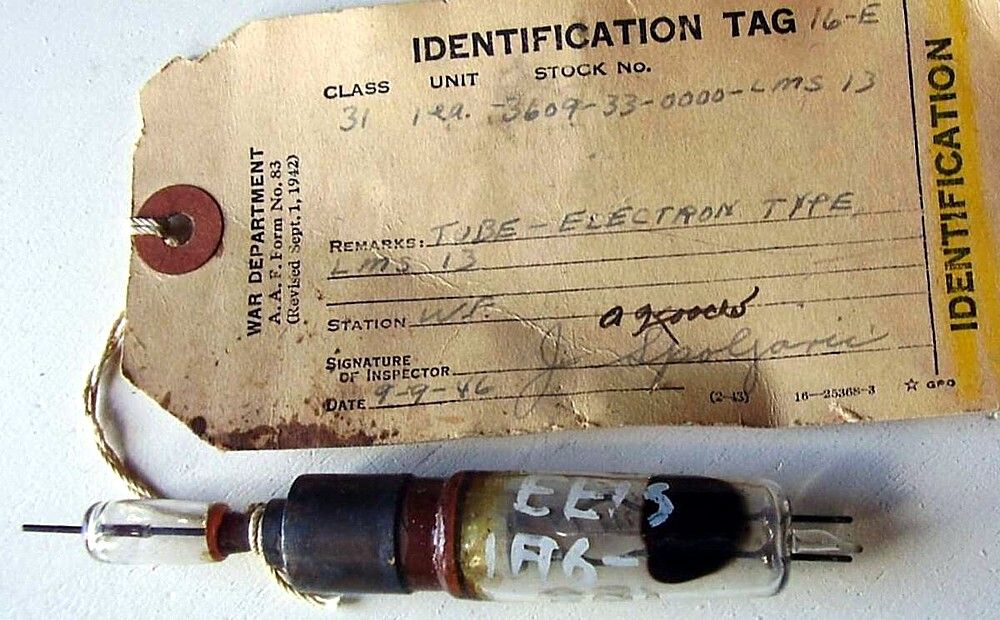
Fig. 2 - LMS 13 sample still retaining its US War Department classification tag, dated 1946. 1.625 cm, 5 kW. 18-resonator anode system. Click on image to enlarge.
The above described specimens are completely different from all the multi-cavity magnetrons of British or American origin made during the war. Their interest, as well as in the extreme rarity, derives from the fact that they allow us to learn the true German way of approaching their own original design. Certainly their shape is unique and it was never replicated later, at least in the western world.
It is hoped that members of the large German community can add information on the applications and the ways of usage of the described types, as well as information on other similar devices.
- The tubes in the above photos are part of ase-museoedelpro collection.
To thank the Author because you find the post helpful or well done.