grundig 80U (80 U) Rescued
grundig 80U (80 U) Rescued

RMORG member Ross Hochstrasser gave me a Grundig Model 80 recently. Thank you Ross!
This very rare radio (in the USA) was the first model in the extraordinarily sucsessful line of 3 tube radios that lasted from 1955 until the end of the tube era in the late 1960's.
This radio was missing the speaker, power transformer, rear cover, knobs, the Ferrite antenna and two tubes.
A spare Speaker from a model 85 was a perfect fit.
I used a small 9V/2A transformer with dual 120V primaries from my junk box. I removed a few turns from the secondary to get 6.3V under the 1,2A heater and pilot light load. One of the primaries takes 120V power from the wall, while the other 120V primary is used as a secondary to generate 250V with a voltage doubler I added. The voltage doubler is made with a 10uF electrolytic cap driving a 1N4007 diode in the first stage of the doulbler. A second IN4007 diode rectifies the 0-320V elevated sinewave into 320VDC. The original power suppliy filter capacitor reformed properly, so it serves as the second stage capacitor of the voltage doubler. The DC load current of the Radio around 60mA drops B+ from unloaded 320V to the nominal 250V required for operation. This voltage is adjusted with the value of the 10uF input capacitor of the voltage doubler.
When using a dual primary transformer to get B+ and low voltage for the heaters, you should not draw more than 75% of the transformer current rating because only one primary is used, so the resistive primary losses are doubled. Normal dual primary connection for 120V input is with both primaries in parallel to reduce resistive primary losses.
The set was designed with a transformer for the heaters and direct rectification of 240V without galvanic isolation. With my new transformer, I am now fully isolated.
This new transformer did not fit conveniently inside the set, so I mounted it in an isolated case on top of the set. Then I took advantage of the weight of the transformer to mount a set of rabbit ears and provide the set with a good FM antenna. I also added an FM center channel tuning indicator in front of the transformer block. I find the meter very useful for accurate FM tuning.

Detail of the transformer case shows the use of banana jack posts to secure the commercially made 3 foot long rabbit ear steel rods. The banana jacks connect conveniently to the 300 Ohm twin lead. The transformer case is constructed from discarded PCB material.
The ECL113 tube has an unusual 8 pin base with a locking notch, and is hard to find, so I temporarily adapted an ECL86 and an ECL80 to see how well they would work. The ECL86 delivered more power than the ECL113, which I eventually found.
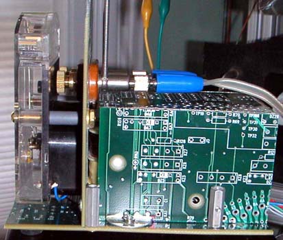
See the home made adapter in this rear view of the set.

The meter is a center zero type with +/-50uA full scale deflection. The meter connection is made between the first output filter capacitor with a new 50k resistor, and the wiper of new 50k pot that is wired across the 2.5uF electrolytic capacitor in the ratio detector. This pot should be adjusted for equal deflection when mistuning up or down. The centering pot is visible in this picture. It was mounted with exterior access at the rear of the chassis.
Although the ECL113 cathode bias 25uF capacitor tested OK, it's internal equivalent series resistance had become too high, and made the audio amplifier prone to very loud oscillations. This problem was corrected by adding a new 50uF capacitor in parallel with the old cap.
The next problem was the missing Ferrite antenna: I found an old ferrite rod with approximatelly the right size, then I took the litz winding that it came with and cut it into two separate windings, was existed originally. I reduced the number of turns on both coils until I got proper tuning at the low end of the AM dial. I measured the resulting inductance at the time, but did not write it down. The value was somewhere around 100uH. The separation of the two coils changes the total inductance and can be used to align the low end of the AM dial. The trim capacitor adjusts the alignment at the high end of the dial. This all worked very well and I got good performance over the entire AM dial.
But the ferrite coupling coil for the external antenna was still missing. I found a choke in my spare parts that had roughly the right number of thurns on a short core of the same diameter, so i just glued it to the end of the main ferrite antenna I built. See folowing ferrite antenna detail.

I had to make do with knobs that were of the right size, but did not match.
I enjoy the sound I get from this rescued set.
Comments invited,
-Joe Sousa
To thank the Author because you find the post helpful or well done.