grundig: Grundig Satellit 500: SRAM memory backup battery replacement
grundig: Grundig Satellit 500: SRAM memory backup battery replacement

My recent acquisition of the Sat 500 came with a dead CL2020-1HF backup battery.
No wonder, my unit have several components with date codes of June-1991, so the radio was manufactured most probably at the end of 1991. The battery would not survive 21 years in service.
Some interesting facts about the CL2020 rechargeable battery:
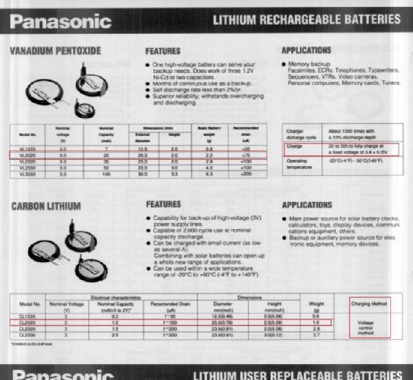
- This is a Secondary Lithium-Carbon Battery (CL) type
- Energy density: of 4.0 Wh L.exp-1
- Nominal voltage: 3V
- But able to operate from 2V to 3V
- Nominal capacity: 1.0 mAh
- Continuous Discharge drain: From 1 uA to 5 mA
- Dimensions: diameter 20 mm x height 2 mm
- Weight: 1.9 g
- Long term charge and discharge ability
- Recommended charging method: Voltage control
It seem that the CL2020 is out of production, but the currently available VL2020-1HF model, despite having different charge and discharge behavior, will probably work as a replacement.
The VL2020 characteristics share with the CL2020 the same physical size, nominal working voltage, and ability to run under continuous charging. All the other parameters looks to be different:
- This is a Lithium-Vanadium Oxide Secondary Battery (VL) type
- Energy density: 100-140 Wh L.exp-1
- Nominal voltage: 3V
- Flat 3V operation behavior
- Cut-off voltage: 2.5V
- Nominal capacity: 20mAh
- Continuous Discharge drain: Standard at 70 uA
- Dimensions: diameter 20 mm x height 2 mm
- Weight: 2.2 g
- Excellent overcharge withstanding characteristics
- Recommended Continuous charging voltage:
- 3.25 - 3.55 V
- Typical 3.4V +/-0.15V over a 200 Ohm series resistor
- Typical 1.5 mA charging current
- Recommended Continuous charging voltage:
The SRAM load, a CDP68HC68R2E type, is able to run aty a VDD of 3 to 5.5V, with a minimum data retention voltage of 2V.
I see why the CL2020 was chosen here, as it can run as low as 2V, enough to be able to feed retention current to the SRAM in this condition. The same can not be said of the VL2020 that will cut-off at 2.5V.
I have ordered a VL2020-1HF (1HF relates to the soldered pins mechanical shape, identical to the original).
I will install it without circuit modification to see the result. I guess it will take long time to charge due to the much higher capacity and the now inadequate CR139 1K series resistor that will drop too much voltage limiting the charging current well below the recommended 1.5 mA.
If it does not fully charge to the nominal value, I will remove the voltage divider network (CR139 1K and CR141 12K) to raise the voltage from 3.2V to the VDD1 3.5V.
The charging voltage drops at least 150 to 200 mV on the D104 BAT42 schottky diode, so my guess is that the original design applies around 3.05V (3.2V - 150mV) to the CL2020. I assume Grundig followed the recommendation to charge for voltage control.
Now, 3.05V looks short as a charging voltage for the VL2020, so, by removing the voltage divider resistors, the VL2020 will see around 3.35V (3.5V - 150mV) wich looks to be inside the recommended charging voltage limits.
(to be continued after testing with the VL2020 battery)

Note: The Panasonic Batteries catalog from Oct-1991 published by their Battery Products Department in Mississauga Ontario Canada that can be downloaded from datasheets archival website, lists both battery types (CL2020 and VL2020) with some specification data. Other battery details were taken from google books, namely "Handbook of Battery Materials" by Jurgen O. Besenhard (Wiley-VCH), and Handbook of Battery Materials 2nd edition, same author plus Claus Daniel (also Wiley-VCH).


To thank the Author because you find the post helpful or well done.
grundig: Grundig Satellit 500: SRAM memory backup battery replacement

Hello Mr. Mesquita,
I think there is a misunderstanding regarding the 'cut off voltage". At the datasheet you can find a diagram called 'Consumption current vs. Duration time' - and there you find the 'cut of voltage : 2,5V'. But that does not mean that the battery realy shuts off (how?) - THEY ended the measurement when 2.5V where reached.
Kind regards,
Daniel Consales
To thank the Author because you find the post helpful or well done.
grundig: Grundig Satellit 500: SRAM memory backup battery replacement
Hello Mr. Consales,
Thank you for your comments on the cutoff point.
I agree. Of course the VL2020 will not simply shutdown below 2.5V. I copied the data from the published documents. By cutoff they mean the end-point operation, the battery should not be operated below that point.
My understanding is that the VL2020 chemistry may not be meant to run at 2V due to a flatter discharge curve, close to the 3V for most of the discharge time, while the CL2020 type apparently seemed to be advertised as such.
Overcharging.
Now, looking to the overcharging condition, both of these battery types seems to be able to run under continuous (over)charging by design, and that is the way they are run in this radio circuit when the four "D" batteries are left inserted in the battery compartment (or an external power adapter is used).
The radio does not need to be powered On. As soon as batteries are inserted, the VDD1 3.5V is applied to the MCU board assembly and among other procedures, the SRAM's backup battery starts charging continuously.
VL2020 as a replacement for CL2020.
As I see it, the important issue here is whether the use of a VL type battery to replace a CL one, without any circuit modification, will properly work or not.
And as I got a VL2020 in my mailbox yesterday, today I have run some testing, and I do not see it charging properly when using the unmodified charger circuit.
Details as follows.
VL2020 on arrival.
The new VL2020 came with 3.009V when unloaded. So it could be nearly in full charge condition.
VL2020 installation and initial charging current measurements.
I have soldered it to the circuit, then installed four "D" batteries in the battery compartment.
In the stand-by condition, the VL battery voltage raised to 3.011V, and the junction of the schottky diode D104 and the 100R R142 had 3.014V.
So, 3mV over a 100R resistor resulted in just 30uA, meaning there is a residual charging condition, either because the battery is full, or else the charging circuit is inadequate. Leaving it at that for an hour did not change it significantly.
MCU current consumption.
By the way, this MCU is not exactly power saver, I registered around 1.65mA of current consumption on the 6V battery supply in the stand-by condition.
The above current value does not include the real charger current. An estimate from the circuit diagram, tells me that the CL2020 at a nominal 3V voltage, over the series resistor of 100R having around 3.05V charging voltage (see my initial post) would result in an average continuous charging current of 0.5mA.
So the total average standby current would be around 2.15mA.
I recall having read somewhere about this high MCU current consumption, just can not remeber where.
If someone have taken current readings for standby state, please share them here.
Turning ON the MCU did not change the above scenario. However the 6V current consumption jumped to 144.7mA (lamps On) and then lowered to 45.8mA (lamps off).
Forcing the VL2020 to discharge, although outside it's recommended operating current (I have no time to wait for days discharging at 100uA or so)
So, I decided to partially discharge the VL2020 battery, to be able to determine if it will charge in the original unmodified circuit.
To do this, first I removed the 6V power supply.
Then a 1500R drain resistor soldered to the battery terminals imposed around 2mA initially, then after 30 minutes the voltage dropped to around 2.9V, and around 2 hours later it had 2.821V.
Then I removed the drain resistor and left the battery rest for one hour, loaded only by the SRAM. The voltage raised to around 2.945V and stayed there after another hour.
I considered that the VL2020 battery at 2.945V was partially discharged, considering an average of 1.9mA during around 2 hours for a 20mAh battery.
Second charging operation, now with a partially discharged VL2020.
So the radio should now be able to charge it to the nominal 3V at very least to restore the lost capacity.
Therefore the 6V supply was again restored.
Now the new voltage values were 3.053V at the junction of the schottky diode D104 and the 100R R142, and 3.046V at the VL2020 battery.
We have then 7mV over a 100R resistor resulting in 70uA. Waiting some minutes saw no improvement in the charging current.
For a 20mAh battery, it is not really charging as it should, if Panasonic data is to be followed. At this rate, it will take (many) several days to charge and may never reach the full capacity.
Modifying the charger circuit for a 3rd charging test of the VL2020.
As per Panasonic data, we could see up to 1.5mA (maximum) during the initial charging cycle, and for that we need a higher charging voltage.
In the radio circuit, the voltage divider needs to be modified for this battery type. For testing, I have shorted the series resistor CR139 1K, leaving the parallel CR141 12K resistor in place for now.
Here are the test results:
| Condition | D104 / R142 junction | VL2020 battery | Charging current |
| Initial charging | 3.205V | 3.047V | 1.58mA |
| 15 min | 3.226V | 3.081V | 1.45mA |
| 30 min | 3.206V | 3.067V | 1.38mA |
| 2 hours | 3.221V | 3.144V | 0.77mA |
After 2 hours charging, if removing the 6V supply, the VL2020 battery voltage dropped to 3.116V initially, and then to 3.102V after 30 minutes.
Applying again the 6V supply results in 0.81mA of charging current (3.218V at junction and 3.137V at battery).
After more than 7 hours now, the battery charging current was stabilized at around 0.8mA.
Optimizing and reducing the charging current at full capacity of the VL2020.
One major concern of using a larger, 20 mAh, battery in place of the original 1mAh, is to adjust the continuous charging current of the former to the value of the latter.
We do not want an substantial increase in the standby current consumption of the radio, while at the same time we want the larger battery to charge as fast as acceptable.
After modifying the charger circuit, the radio is now consuming 2.35mA from the 6V supply, instead of the estimated 2.15mA (see above). It is not a substantial increase, but still.
So a lower charging voltage would be better to have a lower, residual charging when the battery is at full capacity, but not as low as it was being used in the original circuit that was not able to charge the battery in useful time.
I have removed the shunt over the CR139 1K resistor and have installed a resistor in parallel.
After some iteration doing resistor swapping, I settled down with a 1K5 resistor in parallel with CR139. I have now 3.11V average at the D104 / R142 junction, 100mV less than using a short on CR139.
At this condition, the battery is at 3.10V as it was fully charged yesterday, and the charging current is now residual.
I am now discharging the battery once again, before doing another charging with the new charger modification to evaluiate the new charging current that I believe will be lower than using a short, but higher than the 70uA measured using the original charger circuit.
Final update: The parallel 1K5 resistor resulted in just around 0.2mA of charging current having the battery partially discharged, still a low value for this type of battery. So I have finally applied a 560R parallel resitor to have a more confortable 0.5mA of charging current. Any simplified calculations can fail, as there is a non linear device in series with the charging voltage, diode D104, where its drop voltage varies according to the passing current.
Or just leave the charger circuit as it is originally.
The other easy solution is to just leave the original charging circuit as it is, and install the the new VL2020 battery type.
I guess it will work for a long while (one year or more), as long as the battery is able to maintain enough charge.
It all dependes on how large the battery self-dischage is, and if it can be mitigated with the 30uA of charging current values registered above, in order to keep the battery at near full charge at all times.
However, if the 6V batteries are left removed (or the external power adapter for that maatter), then the VL2020 battery will start discharging itself to a point that later on the original charger circuit may probably fail to charge it to an adequate level in an reasonable amount of time.


To thank the Author because you find the post helpful or well done.