hewlett-pa: 210A; Square Wave Generator
hewlett-pa: 210A; Square Wave Generator
SQUARE WAVE GENERATOR
"From HP Catalog 18A" Laboratory Instruments", Copyrighted 1945."

ADVANTAGES:
Simplifies amplifier testing
Wide frequency range
Variable balance output
Indicates phase shift and transient effects
Indicates frequency response
USE IT TO:
Test receivers, video amplifiers,
networks, and transmitters
Provide a time base
Control an electronic switcher
Adjust and check cathode ray sweep circuits
Measure time constants
Generate harmonics for frequency multiplication
SQUARE WAVES FOR RAPID TESTING
THE -hp- Model 210A Square Wave Generator provides an excellent source of square waves for production test and experimental purposes. The fundamental frequency response is 20 cps to 10,000 cps and a reasonably square wave may be obtained at frequencies as high as 100 kc. The square wave frequency is synchronized from an external source of 2 or more volts. The output can be attenuated 70 db from a maximum voltage of 60 volts peak to peak. Output voltages are balanced to ground.
Square waves are formed in the Model 210A by amplifying and clipping the tops of a sine wave, and thus converting it into a wave which has vertical sides and a flat top. The square wave voltage is applied to the amplifier or network under test ; the shape of the output wave immediately shows up any distortion present. Because a sharp wavefront contains a large number of frequencies, this wavefront is distorted when all of the frequencies originally present are not transmitted. The frequencies contained in a uniform square wave are shown in this equation:
F(t) = 4/¶ (sin wt + 1/3 sin 3 wt + 1/5 sin 5 wt + . . .)
In practice, a wave which appears to be perfectly square will contain 30 or more harmonics, and when the amplitude or phase relation of the harmonics is disturbed, the square wave will be distorted. Thus the application of a square wave to a circuit shows up any irregularities in amplitude or phase transmission not only at the square wave frequency but also at frequencies far removed from the test point.
USES
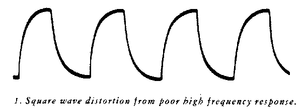
When a square wave is applied to an amplifier, the top of the wave will show distortion if the frequency response of the amplifier does not extend to at least one tenth the frequency of the square wave applied. Likewise the sides of the wave will be distorted if the response of the amplifier does not extend to at least 10 times the frequency of the square wave applied. Thus one observation with a square wave applied to an amplifier will check a wide frequency range, a range of 100 to 1, or even more. This is an extremely important fact because once the proper criteria have been established a production test can be set up with one or at the most two observations with a square wave. A square wave may also be employed to study phase shift effects in an amplifier. An amplifier will not reproduce a square wave faithfully unless both the amplitude and phase shift characteristics are correct. Thus if the amplitude response is known to be good, phase shift effects can be determined with a square wave observation.
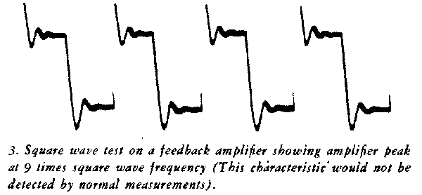
Peaks or deficiencies in amplification of an amplifier can readily be detected with a square wave generator. Tendency to oscillate will appear as damped oscillations on top of the amplified square wave and these oscillations can be measured both in frequency and amplitude with a given observation. A square wave is also very useful in determining the transient response of networks. Time constants of R-C circuits can be easily observed, damped oscillations of resonant circuits can be checked, and the transient behavior of complicated networks can be studied by the application of a square wave to the network, making observations of the voltage or current with an oscilloscope.
Once proper criteria have been established it is possible with one or two observations with the -hp- Model 210A Square Wave Generator to check frequency response, phase shift characteristics, tendency to oscillate, time constants, etc. Thus the use of this instrument will save time and streamline production and laboratory testing.
SPECIFICATIONS
Frequency Range: The output of the generator is square within 1% over the frequency range from 20 cycles to 10,000 cycles. The time for the voltage to rise to 90% of maximum is approximately 1 microsecond; thus a reasonably square wave can be obtained even at 100 kilocycles.
Output Voltage: The output voltage is 60 volts peak to peak open circuit. The output impedance is 1000 ohms balanced to ground.
Output Attenuator: A 70 db attenuator is provided in the output with 5 db steps. The frequency response of the attenuator is sufficiently wide so that the output wave shape is not affected at the highest frequencies.
Driving Voltage: The generator is driven from any convenient external source of alternating voltage or it may be in-ternally driven with the power line frequency. A driving voltage of two volts is required and the input impedance is 25,000 ohms.
Mounting: The Model 210A is mounted in an attractive steel cabinet 15" long, 7" high, and 9" deep, finished in wrinkle gray. The Model 210AR is mounted in a relay rack assembly with a 19" by 7" panel and is 8" deep. The dust cover is removable from the rear.
Power Supply: The generator is provided with a built-in power supply to operate from 115 volts 50/60 cycles. It re¬quires approximately 50 watts.
Weight: Net weight, 30 pounds. Shipping weight, 39 pounds.

To thank the Author because you find the post helpful or well done.