hismasters: 1121: Missing Band Problem
hismasters: 1121: Missing Band Problem
The HMV 1121 was missing the SW2 band. This is the highest band, so it could be the X78 valve (tube) is low as more gain is needed at higher frequencies. Or the waveband switch could be faulty. Perhaps some other fault.
I don't have a spare X78, in fact it might be the only Triode Hexode in B7G package and not used in many sets. I do have a few 6BE6 / EK90 heptode tubes. I read that some people have an HMV 1121 with a 6BE6, A poor solution as base needs rewired and likely much poorer. An adapator with ECH81 or EK90 + EC90 would be far better performance.
It seems though that because there were three variations the coil/capacitors for local Oscillator (LO) and RF is on a subchassis, Easily removed (but note which wires/parts go to what terminal, especially the X78 connections!). But first i cleaned the switch and checked the continuity on Ohms of the DMM. Switch S12, S19, S8 and S1 fine.

Second I thought the LO coil was faulty. Examination with both scope and spectrum analyser confirmed absolutely nothing on SW1 Triode Anode (oscillator) and even IF break through very low.
The voltages on empty socket identical on SW1 and SW2.
But actually only two of the 4 top tags connect to coil. One has nothing and one is just a mount for C9 grid coupling capacitor of Triode section of X78. I resoldered the wires in case of a fracture and thus open cicuit L12 when mounted (L12 is fine wire under L9, heavier wire). Still nothing on reassembly.
C11 and C41 are the only two other possibilities. C11 is Silver Mica and indeed passed 350V leakage (none) and measured close to correct value. Surely not the "beehive" trimmer (C41). Well it was short circuit.
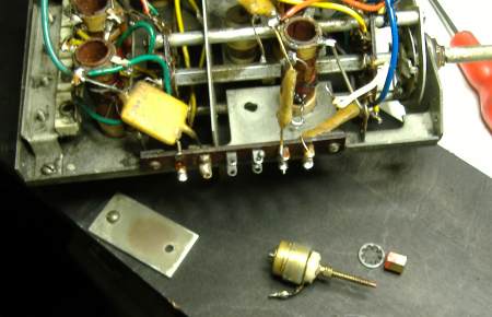
C41 removed from chassis

C41 dissassembled
All attempts to "repair" it failed. Even the slightest engagement of the two halves would result in a short. Cleaning, filing, sanding etc tried.
I do have a few Philips "beehive" trimmer capacitors, these have more concentric cylinders but spacing is greater so maybe not so much different in value (C41 value not listed). Physically they are not the same. Maybe I can poke the earthy spike through chassis hole and the fixed part solder to chassis? The disadvantage is that the normally "earthy" turning part becomes "RF live". But it does mean no modification to the chassis. If solder cleaned, the original type can be fitted in the future.
I used SMD hot air re-workstation to heat the chassis to solder after scraping of a little plating.

The normally "live" fixed part soldered direct to chassis.
A small wire link used to connect the normally "earthed" part to "RF live" coil under the chassis

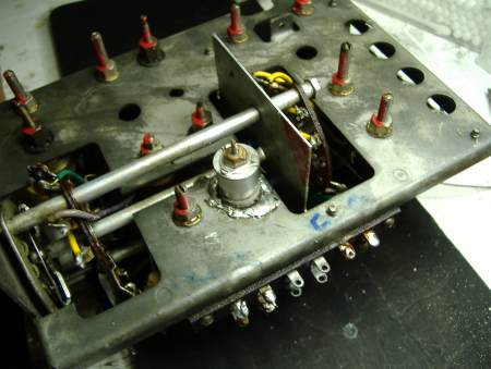
Underside of RF/LO chassis with top of new C41 screwed on.
I put the adjustment at about 1/2 way to start with:

Sub-chassis remounted in main radio chassis
Amazingly I found that the frequency was only about 6mm out on the SW2 scale. Of course the tuning capacitor is "RF live" but not DC live. You need to "withdraw" to check frequency. A few drops of candle wax used on the screw thread/cap top to "lock" the capacitor after adjustment at about 16MHz.
To thank the Author because you find the post helpful or well done.