IF Transformer Repair.
IF Transformer Repair.

Silver Mica capacitor Disease.
The crashing thunderous roar on the AM bands.
In some IF transformers there are integrated capacitors internal to the enclosure. These capacitors are parallel to the primary and secondary of the coils. The range of capacitance, from what I have seen, range from about 70pf up to 250 pf.
After years of service, the silver becomes tarnished where the spring metal contacts touch the silver. Also high voltage potentials cause migration or deposition of contaminants. These contaminants cause shorting and arching (very small) across the capacitor or from primary to secondary depending on the construction of the capacitor sections.
The symptoms of failure are typically static, popping, and thunderous crashes like a near by electrical storm. These are attenuated by the volume control provided the control is “downstream”: from the IF sections. It is a straight forward repair to remedy this problem. Sometimes tapping the IF cans will change the symptom.
(By the way - I have once or twice heard this approximate symptom cause by discrete failing mica capacitors else where in the chassis.)
The basic steps include:
Document, take pictures, sketch a diagram of the IF connections. Mark a reference point on the base of the IF can so you can re-install the transformer in its proper orientation. Often there is a spot of red paint already by a contact. Then desolder and remove the connecting wires.

Remove the metal cover. Drill the rivet loose that holds the retainer over the silver covered mica wafer.

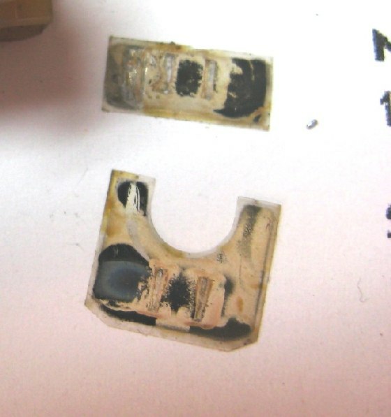
Now the internal capacitor is exposed. I also have marked the capacitor value on the base. Find the value on the schematic or measure the capacitor value with a capacitor tester. See images below.
I also have marked which coil (upper or lower) is connected to which contacts. This is in the event that the coils must be removed from the base. It also aids in determining where to connect the replacement silver mica capacitors.

Next remove the original capacitor(s). You can see the tarnish. If you inspect your capacitors there should be tarnish or deposits that short across the upper and lower plates. Sometimes you will see traces from primary to secondary sides of the IF transformer (this is typical of a single wafer of mica with multiple capacitors.
I had to move the lower tuing slug up to make room to access the original mica capacitors. You may also have to remove the transformer (coil) wires and separate the coil section from the base.

Clip the contacts so they will not short with out the mica wafer capacitors installed.

After trimming original capacitor contacts.

Replace the cover to hold the contacts from moving into the IF transformer's case.

Hot Melt glue the capacitor cover (that you drilled off) back into the base. This will prevent the IF transformer contacts from retracting into the case and touching the slug.

If you moved the tuning slug to make room to clip the contacts, return it to the approximate original position. Returning the slug close to it's original position should facilitate the alignment.

Replace the metal cover. Solder equivalent capacitors external to the underside of the IF transformer.

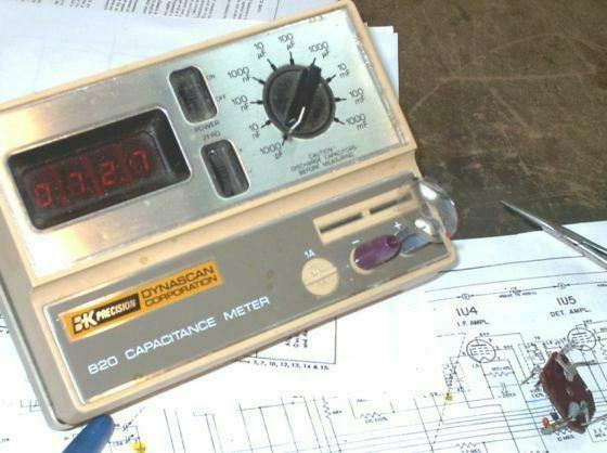
If the values are unknown the wafers can be measured using a capacitance meter. You may have to make two very small probes with banana jacks and a 1inch (4 or 5cm??) bare wire. Pinch the wafer between the bent wires. Or unsolder one of the transformer wires per coil and touch the lugs to the capacitance meter.

This mica wafer is from an American Zenith Transoceanic. There are two capacitors on one wafer. One section for the primary and one section for the secondary. It is common to see silver migration tracks or tarnish from the primary to secondary capacitors.
If your schematic has no IF can capacitor values indicated, measuring the capacitance is better than guessing.
Reinstall onto the chassis and reconnect. Perform a complete alignment. The new capacitors will shift the IF alignment. Check all other alignment specs while you have the RF generator on.

Feel free to contact me if you like.
Paul’s Tube Radio Restoration.
To thank the Author because you find the post helpful or well done.
Figures ?

would you be so kind and check the uploaded figures ? I am not able to see them.
With kind regards
Rolf
Meanwhile I tried to open some other uploades, but without success. So I think the reason for this is my installation of a special software today which enables MS Word to print out PDF-Files including working hyperlinks. I have to check this, because it is a failure of my PC.
Sorry, and with kind regards
Rolf
To thank the Author because you find the post helpful or well done.
Rolf,
All should be well with the pictures and web site. Can you see everything OK?
Paul
Jan 21,2009 I have converted (and removed) the files at the bottom of the article to the pictures with in the body of text. This should make things easier.
Paul.
To thank the Author because you find the post helpful or well done.
No change
Dear Paul,
thank you for your advice and help. I tried different methods in the meantime, but without success. Your personal homepage is available for me without any limits, but inside of RM I always get the following screenshot see below after clicking on any attached picture. I think the address is wrong: http://127.0.0.1:1025/clear.cgi?, but I do not know the reason for that. The same result appears when I use IE 7.

Rolf
To thank the Author because you find the post helpful or well done.
Rolf,
All the uploaded pictures of this article on the RM.org server are from my web site. I am slowly loading "How To" parts of my web site to RM.org for the eventuality (unplanned) that my site will end.
As for your problem, it looks as though your browser is looking for a page on your local computer (as indicted by the IP address). But I am far from an expert on computers. Others should be able to help you. There are a lot of smarter people here at RM.org than I.
Paul.
To thank the Author because you find the post helpful or well done.

I can read all pictures.
Mr Nickel, you should deactivate all you loaded lately (toolbox?, popup blocker?anti spyware?) or readjust your internetoptions to the original adjustments, or run a system refresh back to a date, all was working fine.
To thank the Author because you find the post helpful or well done.
Article with integrated pictures

Dear Paul
You have changed your article "Electrostatic Tweeter Restoration" into a very instructive and helpful article.
Such good articles I have linked to the text link you see when clicking the tab "Forum" and then the link "Some examples of well done text and help plus our forum rules".
I invite you - if and when you have time and the pleasure to do it - to rebuild your important article here the same way.
Other members (and guests) I beg to indicate more such good articles to include to this list. I'm sure there are more such articles with integrated pictures and/or outstanding text.
To thank the Author because you find the post helpful or well done.
IF Transformer Repair.
I am new on tube radio restorations and I was working in a Zenith Trans-Oceanic H500 version A.
I want to ask you if the bellow description can be of an IF transformer Failure.
Everything was going well,
I did have the Wavemagnet antenna fixed (bad contact on the hinges under the top of the cabinet that resolved with contact cleaner).
The radio was receiving with low sensitivity that I was thinking to fix with an alignment, first "informal" and then with a proper one as soon my signal generator that is coming from abroad arrives.
I was with the radio on (127V on a variac and an isolation transformer) to get some hours of working, because I read in one of the treads on ARF forum that it was good to have at least 80 hours with the radio on before to try the alignment (trying to restore the Q factor of the coils, etc).
I was reading a text from Mr. Peter Wieck on the site "ZTO the Royalty of Portables" (where he was talking about fixing IF transformers, etc) when suddenly, the radio did stop to receive and I heard a kind of loud static sound (crackling?).
I did turn off the radio and after 1 hour, I did turn it on again and I got only that loud sound. I did change the tubes one by one and nothing different happened. When the dial is close to one station the crackling appears to be less intense.
The tension on the filaments is 1,35V and on the plate of the 1L6 is 83V or so.
There was no smoke and the temperature of the set was pretty normal, I guess.
By my readings at the exact moment that it happened I think that it is a symptom of a bad transformer similar to a silver-mica disease.
Any other explanation? What else can I do right now to check?
Many thanks,
Alvaro.
To thank the Author because you find the post helpful or well done.
IF Transformer Repair.
Count of Thanks: 30

Thank you for this post! This is the same method I use too. BUT, when measuring the original SM caps, depending on the extent of the degredation of the silver, the measured value may not be the required value to restore the design resonance to the IF. I have seen SM disease so bad that the perimeter of the silver was eroded away so bad as to reduce the measured capacitance substantially from the design value. And we all know there is no standard IF cap value across models or brands. So, relying on replacement component selection based on the measured value of the remaining capacitance can be incorrect. And most of the time the schematic does not disclose the cap value in the IF can. So, what I do is forget about measuring the SM cap, and instead remove the cap as you did, then reassemble and reinstall the IF can, I then solder on a couple of miniature poly trimmer caps, set the tuning slugs about half way out then go for an alignment using the trimmers to peak the cans. You can balance the trimmers and slugs to get the best peaks too. I usually leave the trimmers in place, but one can go a step further and replace the trimmers with a standard value SM dipper. incidentally, the oxidation of silver in ambient air is the reduction to silver sulphate, not silver oxide.
Thanks, Mike
To thank the Author because you find the post helpful or well done.