lissen: 8515: Restore and Repair
lissen: 8515: Restore and Repair
First download the Trader sheet 450 (if not here, it's on the Ever Ready 5214 All Dry Battery Portable). Generally the Trader sheets are best.
There is no felt/cloth filter on the speaker voice coil so work in a dust / swarf / wire free area!
First take all the angles of photos as it is received.
Get a tray with lid for all parts.
Then carefully remove chassis from the case
- Pull the knobs off gently.
- Remove all tubes (holding at base) and put aside carefully where they won't roll on to floor or eaten by small children or large animals etc.
- Take out two screws on side coil.
- Take out two screws either side of chassis, and chassis should lift out.
- Unscrew four baffle board nuts, not the nuts on speaker.
Photograph wiring and underneath of chassis and put it in a safe place.
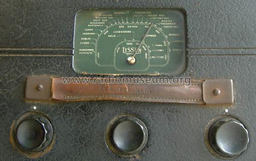
Next you can remove the handle using the two internal nuts.
The perspex (or related) scale cover is held in with 8 small pins. Using pliers just pull out straight without bending. Leave in the two on rear edge as they would be hardest to replace.
The cabinet can now be restored, depending on the wear & tear and damage. Mine needed a few small holes and scratches on outside fixed. "Structural" or "Modelling"/"3D" Acrylic paste is superior to "filler" for a filling as it's more flexible, better adhesion and less likely to crack. An appropriate colour of Artists Acrylic paint or household "vynil" paint can be used to touch up "leatherette"/"Rexine" etc.
PVA is best to repair wood, loose veneer or flaking leatherette"/"Rexine" etc.
On my cabinet the only major damage is the chassis mount blocks


The larger part was just clamped and the small chip got a pin.
The Electronics
As usual I print a photo of chassis and mark up the likely poor capacitors. Then identify them on schematic. Not all Wax paper or Electrolytic capacitors may need replaced.
It's likely parts are all 20%, and in some cases even greater tolerance doesn't matter so don't be put out by a resistor reading 13M Ohms instead of 11 M Ohms. If it is faulty a 10M or 12M modern part is likely fine.
Here is the analysis of the capacitors
| Part | nF | Function | Volts | |
|---|---|---|---|---|
| C10 | 2 | Transient Protection(so called "Tone Correction") | 85 | * |
| C9 | 5 | grid audio coupling DL2 (o/p) from DAC1 anode | 12 (100) | * |
| C7 | 10 | volume control to DAC1 grid | 0 | |
| C3 | 8uF | Electrolytic Supply decoupling | 100 | * |
| C4 | 40 | Heptode screen grid decoupling DK1 | 40 | * |
| C1 | 40 | RF agc decoupling | -1 |
32V was conected to HT rail with no LT and no tubes to "reform" C3 8uF. Immediate current was about 0.5mA. After about 1 minute the current fell to 0.3mA. After 10 min it was 148uA (0.148mA). Snipping C10 at the valve base reduced current by 7uA.
The C10 on its own was 7uA.
Voltage increased to 44V. Current rose to 280uA and quickly fell to 235uA (no C10). C10 on its own about 10uA!
So providing the C3 actually has 5uf to 15uF capacitance, it will do. C10 may do OK but is a risk to the output transformer. Later models have it across the primary which is "safer" for the small fragile transformers on 1950s Valve portables, If it was on Anode to grid it would be a disaster.
Later I will check C9 (very critical) and C4 (gain penalty only if leaking) which are the last two "important" capacitors for leakage. Note that if DAC1 filament fails or is unplugged then C9 has up to 100V!
A fresh battery pack is about 100V.
The service sheet confirms my measurements that an "All Dry No. 3" is used. Later known as AD3. Since the LT current is about 250mA and the HT about 9mA, the "real" AD3 battery pack would likely have lasted 200 to 300 hours and probably had 6 or 8 x F cells in parallel for LT. Or something similar capacity. The HT may have been 60 x B cells. A "modern" replacement can use 60 x AA cells in holders and 6 x F cells (from 1 & 1/2 off "996" packs) or 8 x D cells in parallel for LT.
More ...
To thank the Author because you find the post helpful or well done.
The Electronics, part II
The Speaker
Examination of the voice coil / magnet pole suggested a piece of wire and "something". No filter across centre of cone! I made a hook out of thin "coffee tin" and bent it to curve of coil / pole and "fished" while ready to grab with very pointy sharp non-magnetic tweezers. A piece of silvery wire and other shiny piece recovered.
Further tests on the Capacitors
I won't worry about C1 & C7 right now
| Part | nF | Function | Volts | |
|---|---|---|---|---|
| C10 | 2 |
Transient Protection(so called "Tone Correction") High Leakage: Replaced for Transformer safety. It's actually passable right now (50uA @ 100V), but too big a risk. |
85 | * |
| C9 | 5 |
grid audio coupling DL2 (o/p) from DAC1 anode High leakage: Replaced. Really no measurable leakage is acceptible in this location |
12 (100) | * |
| C3 | 8uF |
Electrolytic Supply decoupling Leakage acceptable, but fails anyway: Replaced. On checking it's discharged and measuring capacitance it's only 0.1uF. Obviously "dried" out. Replaced with 8uF 160V |
100 | * |
| C4 | 40 |
Heptode screen grid decoupling DK1 High leakage: Replaced.Likely to impact gain. |
40 | * |
Next replace all the valves and connect to a 1.5V "F" cell. Do you trust rare as "unicorn feathers" battery tubes on a PSU? I don't. Metered current suggests all have filaments!
Turn off
Connect 80V HT mains supply.
Turn on.
It "motorboats". No LW stations (too early in evening for MW in Ireland) and no Signal Generator.
Hmm...
Power off and unplug DK1 and it still does it. The DF1 is loose in its base. So I remove it and put almost two turns around bottom of metalisation where the wire is of 8mm self adhesive copper tape with sticky side out. Then stretch about 3 turns of "self amalgamating" tape on top to gently compress it.
Plug it in and power on. Success. RTE1 252KHz and UK R4 198kHz at about correct places on dial and sounding "OK". Signal generator about correct at 1200kHz and 600kHz on MW, further off at 1500kHz. Not very sensitive either. Need to reassemble into cabinet and fine check MW alignment and replace one "dozed" rubber cable between the two aerial loops.
Meanwhile the main part of cabinet has been repaired (mounts) and pits on outside filled with "3D Acrylic" paint and then artist's Black to match the leather effect cloth. Looking good. Back is unsoldered and pits & scratches touched up.
To thank the Author because you find the post helpful or well done.
Alignment
[Edit:]
I forgot to mention that the -HT series resistor to -LT, standard on almost all parallel filament battery sets with no "GB" (Grid Bias Battery) is perhaps the most important and critical in value

Output stage, C17 connects to Volume control wiper
R12 is 860 Ohms. Check that R12 has not gone low resistance. Likely a modern 5% 820 Ohms is fine. If it measures even 1000, this will do no harm only limit maximum volume before distortion. Even as low as 680 Ohms isn't fatal, that's about a 20% increase in current. It sets the bias via R11 for V4. Also visible is C19, the audio coupling from DAC1 anode to DL2 grid. If this has almost any leakage the bias is dramatically too close to zero volts or even positive. If -HT current is 9mA the bias is -7.7V. R11 is 2.1M Ohm (any value from 1M5 to 3M Ohms is likely OK) so only 5uA makes the bias be almost +3V instead of -7V!). The likelihood is the audio transformer burns out or filament fails on DL2 due to excess anode current.
A regular DMM or AVO uses too low a voltage to measure the leakage on C19, you need at least 100V DC. It can be tested by replacing V4 with a 15K ohm resistor from Anode to Filament - (chassis), or 15K from +HT to -LT. Then measure the voltage at "g1" junction R11 and C19 with a 10M Ohm input impedance DMM or AVO on 300V range (=6M Ohm load). It should be -4V to -9V, If it's -3V to +3V or higher then C19 has too much leakage.
Alignment
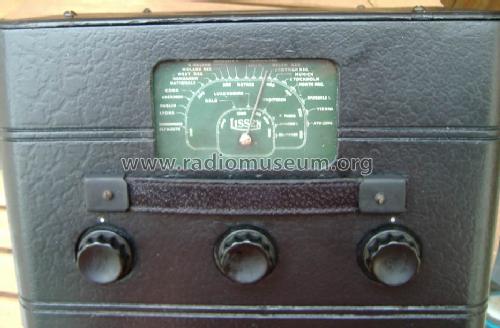
The Alignment was fairly close to ideal. Only the two variable capacitors on the tuning RF & Osc gang needed a little adjustment and a variety of UK MW stations coming in well at 11pm.
The speaker/baffle cloths very much brighter green under the corners of the "octagons", as was the scale when cleaned. Very similar greens and nearly viridian rather than the olive it seemed.
It's important to have the DK1 and DL2 (end valves) out when taking out or putting in the chassis screws, and to have the RF wire from coil to tuner unplugged from the top cap of the DK1 when re-fitting coils.
I have tested with an Ersatz B136 (which doesn't fit in the cabinet of course). So next to make an AD3. I first need to finish the socket on the B103 for the Model C/A.
A piece of 180 grade "wet & dry" takes the shine of the black acrylic "touch up" to closer match the black "leatherette".
I'm not convinced that the handle is original. I think it's off a suitcase. Close up shots of the Ever Ready 5214 handle will be examined. I have a 1950s speaker handle that looks identical to a Model C/A handle. Perhaps that would be closer to the orignal?
To thank the Author because you find the post helpful or well done.
More about the cabinet
First here are the Tubes (Valves)

DK1 DF1 DAC1 and DL2, Made in USA, yet Mullard/Ever Ready? Perhaps even Philips.
(Pinch construction visible on the DL2, though "button base" did exist on not just B7G and "loctal" but other tube types too by 1939. Certainly used on some German "edge type" tubes and later on Octal types e.g. 6146)
You can see someone has tried to glue the loose DF1 base. Glue needs to be below the metallisation and wire on the bare glass, and then either nickel spray (looks similar) or PCB repair conductive silver paint to connect the "earth" wire (which likely goes to "filament -") to the Metallisation. The RCA and later Philips B7G (7 pin miniature all glass button base) use an internal metal screen can. The Russian Rod Pentodes relied on a physical metal screen on the PCB or Chassis. The repair described earlier can be done with flattened braid or foil off TV coax and then any method to lightly compress it against the wire and existing metallisation.
Speaker Fabric
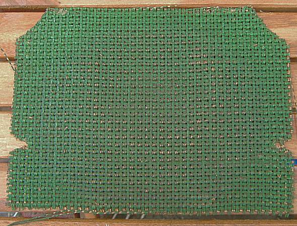
Original untouched cloth
The part hidden under the wood (clean and not faded or abraded) is much brighter and a very close match to the scale green. Which was MUCH brighter when cleaned. I'm inclinded to believe it's factory sprayed as there is no green at all on the rear and it has rubbed off on the front in places. Artist's "Viridian Green" acrylic paint is a near perfect match when dry. I tried it first on an unseen part of rear cloth. It's the standard double string cloth weave as on the C , C/E and C/A and also identical to some UK 1950s school extension speakers I have.
Like the rear panel cloth, someone long ago had added four drawing pins to assist holding the cloth. Originally I think staples were used and had rusted away. Some industrial staples on the rear still. Why rotted?

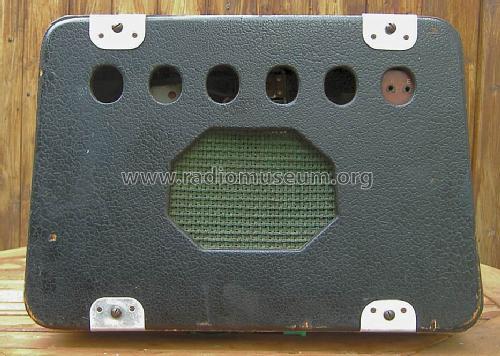
Speaker Baffle/mounting plate
You can see it once had rotted in two places.
Actually I soaked the board and entire insides of cabinet after stripping and cleaning with "Ronseal Total Wood Preservative (Clear)". This stuff is flammable and stinks. While it's alleged to deal with "woodworm" it's ominous they recommend checking every summer! The grubs are deep within the wood and live for up to five years, emerging leaving 0.5mm to 2mm "flight holes". Then they become the beetles and breed, dying after a few days. The dust or "Frass" is actually the grub's droppings. There was no evidence of woodworm (unlike my Invicta 26 aka "Vicky" (Pye) or Ever Ready C/A). Really you need to "cook" any wood that's infested if sound enough to repair. I do use a blow torch!
However the Ronseal liquid almost certainly kills the bacteria and/or fungus involved in "rot" and also "furniture" beetle eggs. Paint or varnish into cracks, seams/joints and all bare surfaces dramatically reduces risk of (re-)infestation as the hatching eggs really need bare wood. After the Ronseal had somewhat dried I filled the "holes" with Structured/Modelling/3D Acrylic (white) paint and then a finish of brown.
The metal plates on the rear cover
These of course are not original. Examination of the cover suggests why they are fitted.

Damage marked with arrows.
I'll think about if it's viable and sensible to repair the panel damage and remove the four Alloy plates.
Model Label
On the Ever ready 5214

This is near front of cabinet on the inside.
It's been pulled off on my model!

Inside Front of cabinet just under speaker cloth
So I assume it's a 8515 as it's black. It might of course be an identical 8514 or 8516. The other Lissen models with this chassis are probably larger cabinets, some are likely large Table models, "Farm Radio" sets. If we include the models of same design chassis but octal tubes (which are probably near identical) there may be about 11 or 12 Ever Ready (Forces Ent., Post War "A" and Table models) 1939 to early 1946 and 8 Lissen models (probably 1939 up to early 1941 only).
Tuning Scale pointer
When I read about the Ever Ready 5214 and "Forces Entertainment Portable" and the contra-rotating pointer/knob later "fixed" I assumed (wrongly) it was a drive cord issue.

Detail of Tuning Drive
Actually the tuning gang capacitor has the pointer on the end of the shaft and a large steel disc with a bevelled edge. This engages in a groove on the small disc (to give gear ratio) on the tuning knob shaft. So now cogged gears or drive cord. The only simple way to "fix" this is to add an idler gear between. If the tuning knob disc is reduced in size as is required then the gearing is increased unless the main disc is reduced too.
The later Ever Ready "All Dry Battery Portable" models replace the disc on the tuning capacitor with a normal cord "drum" and the smaller slotted disc of the friction drive above becomes a drive cord spindle. This doesn't need any change to the main metal chassis as an idler gear would require.
To thank the Author because you find the post helpful or well done.
Undoing earlier repairs?
I took of the four metal plates and made two paper templates for the missing pieces of rear panel. I cut these out and used them to draw an outline on plywood.

I then used acrylic modelling paste/ 3D paint to fill the cracks and sanded. Final finish with artist's black acrylic paint.

Click for larger images
Examining the handle
It's definitely off a suitcase or briefcase. The end metal rectangles don't suit the brackets which match the Ever Ready 5214 etc and the Model C. So I replaced the brown handle with one dyed black from a damaged 1950s Schools' Loudspeaker cabinet, that was almost identical to the Model C/A handle of 1947. I suspect the original was leatherette covered to match the cabinet.
Click for larger images
The metal parts were very rusty so these were rubbed down to remove loose material and "painted" with Rustin's Rust Remover (Phosphoric acid /Alcohols mix). This turns the rust black and inhibits further rust. Then a light spray of Black acrylic paint.
To thank the Author because you find the post helpful or well done.