wkelectric: Oriole Model 100 - W-K Electric Co. - Restoration
wkelectric: Oriole Model 100 - W-K Electric Co. - Restoration

Fellow Radiophiles:
The following article was reprinted here by kind permission of Robert Lozier.
From the collection of Robert Lozier, Monroe, NC KD4HSH@CAROLINA.RR.COM
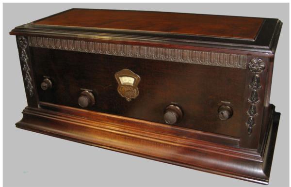
Oriole Model 100 - W-K Electric Co.
Kenosha, Wisconsin.
Circa: Spring of 1927
 First of only two American broadcast receiver manufacturers to use Cathode Follower RF Amplifiers in their 1920s designs.
All Oriole radio designs used one or more stages of tuned radio frequency amplification. Except for their first Oriole branded radios, based on the Model 5 chassis, their uniqueness was in using a cathode follower RF amplifier scheme. This was coupled with clever applications of regeneration to maximize sensitivity. As with many 1920s makers of radios, they employed regeneration
in violation of patents controlled by the RCA. In the case of Oriole, this complicated their obtaining publicity about their ‘revolutionary’ Trinum circuitry. If they were to explain the circuit in articles in the popular press, the RCA patent department lawyers would surely quickly appear with cease and desist orders or threaten litigation.
Oriole Model 100 Description

This, apparently, final design recognizes the industry trend to sell the notion of ‘single dial tuning’. Sure enough all six tuning capacitors are ganged via large cut brass gears with a clever zerobacklash spring loading feature.
 With six tuned circuits in individual compartments, the selectivity becomes quite good. So much so that the first tuned stage does not track well across the whole broadcast band. It is here that the designer had to fudge the claim to ‘single dial tuning’ by adding a mechanical method of vernier adjustment to the capacity of the first stage that appears to be unique. (It is fair to note that many other ‘single dial’ sets had some sort of control to peak the tuning of one or more stages. They were often labeled verniers, clairifiers or compensators.)
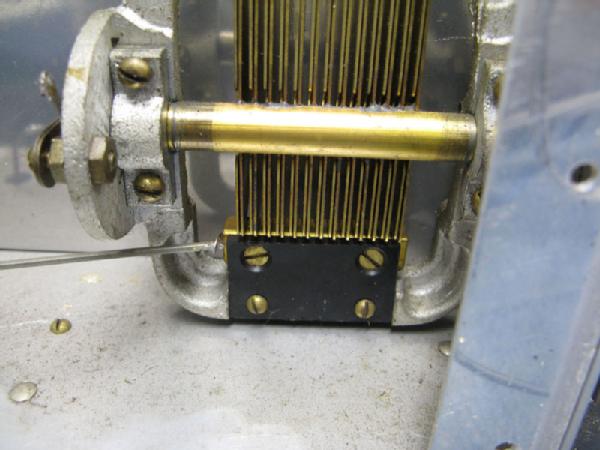
Here the unique approach to fine adjustment of this first tuned stage is made by a lateral shifting of the shaft that mounts the rotor plates; such that they are more or less centered between the fixed stator plates of the capacitor assembly! This method works very well!
With so many high Q stages, I wondered if it is necessary to stagger tune the stages to get acceptable bandwidth but informal listening tests don’t flag that as a problem. I did verify that the final RF amplifier was off frequency by alternately inserting a ferrite or a brass rod into one secondary coil at a time to shift the resonance point. To rotate the offending tuning shaft to the proper position can only be accomplished with the gear train fully exposed. After this correction, all the circuits were very close to resonance across the whole broadcast band.
There is an antenna matching circuit that works well for long wires of varying length. With the apparent rarity of this particular model it was indeed great luck that the 20 page user manual was still in the receiver cabinet. There is no mention of using this receiver with a loop antenna. And you can look at the schematic to see that a loop cannot be tuned by the first stage with the available antenna connections.
Working with this receiver soon demonstrates that it is much more selective at the high end of the broadcast band than many other TRF radios of the day. I was surprised to be able to tune-in early evening broadcasts from 1690, WPTX Lexington Park, MD; at a distance of 375 miles to a 10 kW station. I have 4 & 5 kW stations less than two miles away. With such high signal levels, they obliterate stations +/- 30 kHz. either side of 1060 and 1190 but otherwise the band is full of DX in the evenings.
The only improvement to high end tuning ease would be to substitute the straight-line capacity condensers with straight-line frequency units, BUT they would not fit in the same size compartments. I think the chassis would have to be 8 to 10 inches wider…..
Restoration Challenges
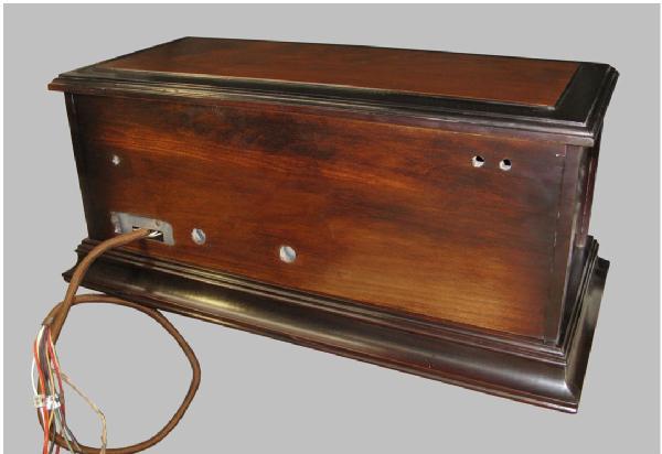
When found in the flea market at the annual conference of the AWA in Henrietta, NY in August 2017, the cabinet was in the usual state of many attic or dry basement stowaways. Finish flaking away beyond simple conservation techniques and loose cabinet joints mandating a complete knockdown and refinish. Otherwise not really dirty enough or rusty enough to be called ‘barn fresh’. Fortunately almost all chassis parts are aluminum or brass.
There are many radios of the 1920s that have ‘deal killer’ defects that keep many people from attempting to do accurate restorations. Atwater Kent horn speakers, Crosley ‘tool box’ radios, Kolster and FADA radios are notorious for their fractured ‘pot metal’ die cast parts. RCA Radiolas such as the Model 20, 25 & 28 have cabinets using laminate glue that lets-go far more easily than seen in other cabinet makers product of the day. The radios and horn speakers with crystalline lacquer finishes cannot be duplicated these days because of the hazardous chemicals and dangerous application techniques used. Certain dyes used on cotton, Rayon or silk fabrics of that period were very vulnerable to radical fading and the fibers suffer considerable loss of strength by light and atmospheric exposure.
The same can be said of battery cables and general wiring within early radio equipment. Many know of the colorful rubber covered hook-up wire used in Atwater Kent radios of the early 1930s. The insulation is now potato chip rigid and just as fragile.
Challenge #1
In this Oriole radio the ‘deal killer’ is the 9 conductor battery cable hard wired to a tag board under the chassis. The cable is so severely deteriorated, salvage is not possible. I made a replacement cable using techniques developed during the restoration of my second Swedish Radiola M55 of 1927 vintage.
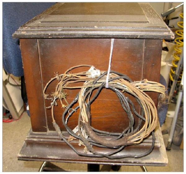 The battery cable is a little shorter than I would have expected. But there is evidence that the cable was never longer because each wire has a metal ID tag attached just about where you would expect it to be. There are 7 – 20 gauge wires plus 2 – 16 gauge wires to service the filaments of the 8 type 01-A tubes.
 Here I used 20 gauge cloth covered wire obtained from Radio Daze. This is the closest wire I’ve seen to replicate the original rubber insulated wire with color coded cotton over-braid. Unfortunately this reproduction wire uses common white PVC insulation under the colored braid that makes the wire much less flexible. I have found that it is possible to get black silicone rubber covered wire in these gauges. It is just a flexible as the original rubber insulated wire. I would gladly pay more to get reproduction wire made with Black silicone insulation.
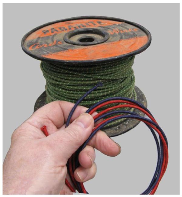
I have an old spool of 16 gauge stranded hookup wire that must date from the 1950s that has a green dyed braided covering. It is still in fine, flexible shape. I found that I could bleach the color from the wire braid and then use RIT brand dye to make Red and Black ‘A’ supply wires for my new cable.


 I engineered a braiding fixture with 16 shuttles, just like this 12 shuttle fixture I made for my Radiola M55 project. To permit braiding a jacket over this bundle of 9 wires, you have to add a filler strand of jute string. The filler necessary to form a smooth, slightly oval cable.
Once the bundle of wires is gathered into parallel alignment and secured by a spiral wrap of thread, it can be placed into the braiding fixture. In this case, about 36” of the bundle needs to have the braided jacket. To do the braiding takes about 8 hours work but the results are quite good. Good enough such that viewers are not likely to spend time questioning if the cable is not just ‘new old stock’ cable of the correct style.
Challenge #2
The Bakelite front panel was going to have to come off for proper cleaning of the chassis. Unfortunately the knobs were not attached with traditional set screws but with a music wire clip that is anchored in a small hole drilled crosswise in the brass shaft. What happens is that these clips rust and they will no longer slip the few thousandths required to permit the knob to slide off under any reasonable force.
Hours were spent on devising a method to remove the knobs in a way that would not crack them. It involved making tools to remove screws behind the panel that were never intended to be accessible unless the front panel was off the chassis.
Once these screws were detached, it provided just enough wiggle room to insert additional tools and supports that would permit sufficient force for clip extraction without breaking the knobs. It worked! But that task burned more than a full day of shop time.
With the front panel removed I could inspect the tuning linkage between the six tuned circuits. There are six brass gears with an anti-backlash feature that was not unexpected and seems to work well. What I did discover, that I cannot recall having ever seen before, is a method of vernier capacitor adjustment on the first tuned stage.
I had expected that this vernier might have been built as a single rotating vane actuated by a coaxial drive shaft. Not so; the change in capacitance is accomplished by causing the rotor vanes to shift laterally on the shaft bearings so they are more or less centered on the stator vanes! Crazy! Eh? But it works very smoothly.
The aluminum shielding was removed in order to properly clean the chassis.
Challenge #3
As mentioned, the cabinet finish was too damaged to just employ conservation methods. In addition the cabinet joints were loose and needed to be separated for proper clean-out and re-gluing.
Like the Oriole - Warwick 71, there is shading of the base and sides. It is not something that is appealing to modern eyes but never the less it was their deliberate decision. I find this very difficult to replicate and my work is only moderately successful in achieving the original effect. The top lid coloration departs from the Warwick 71 in that there does not appear to be shading of the central panel of the lid. Instead they outline the area with an opaque VanDyke brown.
This cabinet is dimensionally identical to that of the Oriole Warwick 71 and the Nunn-Landon Co. Cascade radio is made the same way except for being a 2” deeper cabinet. The only differences are the decorative simulated wood carvings attached to the front of the cabinets. They must have been manufactured by the same cabinet maker.
Challenge #4
At present one of the audio transformers is open circuit… There is no need to replace it. A substitute Thoardarson 1:3 ratio transformer was tacked in place in order that performance checks could be made on the radio. (More about this later.)
Ready for testing…
As mentioned earlier, the primary significance of these Oriole receivers is the fact that they are the first known manufactured broadcast receivers to make use of Cathode Follower RF Amplifier stages. The novelty of these receivers was revealed to me by articles authored by Joe Sousa and Ed Lyon printed in 2014 and 2017 issues of the MAARC monthly journal, Radio Age. If I had not seen these articles, it is unlikely I would have recognized the Oriole Model 100 as being of this lineage. While the late Greg Hunolt had found a reference for this model to add to his Battery Set Compendium, it appears that this Model 100 on exhibit is the only one remaining. It was apparently manufactured just before management decided to close the business.
The first measurements of the Oriole 100 were general gain per stage over the broadcast band which goes from 500 kHz to 1700 kHz. Signals from my URM-25D generator were coupled to the radio using a 0.02 mfd film cap in series with the antenna input. There is a tap switch to match the antenna to the radio. Setting the tap switch to Position 1 or 2 (they are actually shorted together) provides the best coupling to the first stage.
After a series of measurements, the tubes were cycled through the 3rd. stage to see if there was a significant change in per-stage gain because of the tubes used. With the tubes I have, there was something like 20% variability. The tubes matched closely (3%) on my Heathkit emission tube tester. After several rounds of measurements I was totally frustrated by discovering that measurements were not repeatable. Eventually I was able to identify one tube as the primary culprit. I still do not know why its gain drifts about. (Filament wires in the base appear to be in perfect condition and it tests good and stable for emission.)
While I can use a 10x scope probe on the primary of any stage RF transformer, touching the probe to any grid circuit (secondary) kills the signal almost completely. My O-scope has a maximum input sensitivity with a 10x probe of 10 mV. per division and 13pf. loading. I measured the peak to peak voltage across the cathode winding of tube #1 and then the same for tube #2. The voltage gain was 2.2 to 2.5. The same voltage gain was true of each additional stage, 2 to 3, 3 to 4 and 4 to 5.
The RF transformer windings are wound on black fiber tubing. The primary former has an o.d. of 0.59” and the secondary former has an o.d. of 1.5”. The two tubes are coupled together with brass screws & nuts in binocular fashion with a gap of about ¼”.
The RF coils have a turns ratio of 1:1 with approximately 106 turns on each coil. (The primary must be a bifilar winding because the cathode of the tube is the filament itself.) It is close wound - double layer and the grid coil has 106 turns in a close wound - single layer. All wire is DSC 28 gauge.
There is a lamination stack inside of the cathode coil presumed to be silicon iron alloy sheet similar to that employed in MW RF transformers such as are seen in the Federal 61, Erla Superflex and Acme reflex designs circa 1924. The approximately 20 strips that make the core are 1.5” long, 0.25” wide and 0.015” thick thus making a stack about 0.315” high.

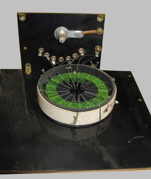
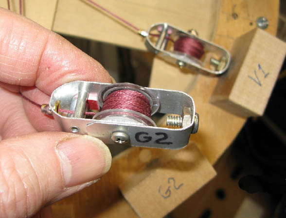
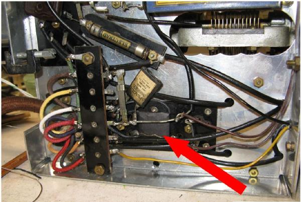
At left are the first and second RF amplifier transformers. The small coil is in the cathode circuit and the larger coil is the grid circuit.
Note on the right cathode coil there is a small additional winding, this is the global regeneration winding.
The right tuning condenser visible in the background has a leaf spring that counteracts the jack screw that produces the lateral shift of the rotor being used as a vernier tuning adjustment.
As explained by Joe Sousa and Ed Lyon, the advantage of the cathode follower RF amplifier when used with simple triode vacuum tubes is that it eliminates the effects of grid to plate capacity and its considerable limitation to the amplification that can be obtained before the circuit breaks into oscillation. While the circuit provides no more than unity voltage gain, the voltage at resonance in the output tank of each stage can be more than 2.5 times as great. Therefore the net voltage gain of the stage is significant without any possibility of uncontrolled oscillation. (See Table included in the next post.)
This characteristic when employed with two or more stages, leads to their ability to employ deliberate, smoothly applied global regeneration to the stages. As mentioned, this would be in violation of RCA held patents but the implementation in this design was so very clever and works so well that you can hardly fault the designer for wanting to add the feature. This global regeneration just about doubles the tuner output voltage.
At the extremes of the regeneration control, the set will oscillate and therefore it can be used to find those weak stations for DX fun. As mentioned earlier, the first tuned circuit has a vernier control that must be tweaked for maximum sensitivity across the band. Having the set oscillating makes it easier to detect those weak stations a few tens of kHz off from where the vernier is not at its best position.
Only one other American manufacturer is known to have employed the cathode follower RF amplifier circuit in a broadcast receiver of the 1920s, but it is clear that their implementation lags that of Oriole sets built by W-K Electric Co. by at least a year. That other company is Nunn-Landon Company of Milwaukee, WI with their Cascade brand receivers. It seems very obvious that there was some technology transfer between the companies but there is apparently no surviving documentation to verify if this was through some business arrangement or by technology theft.
So why didn’t other American radio manufacturers of 1927 adopt this solution? It is only speculation on my part, but I can think that without radio press exposure of the performance obtained with the ‘revolutionary’ Trinum circuit coupled with un-licensed regeneration utilization, it could gain no traction against the very successful licensing of the Hazeltine Neutrodyne patents. Also in that year the first successful screened grid (tetrode) tube for RF amplification was widely reported in the radio press and would be widely available by the end of 1928. This tube innovation provided even greater voltage amplification making it possible to obtain comparable performance with one or two fewer tubes.
Challenge #6
As mentioned earlier, one of the audio transformers is open circuit… There is no desire to replace it since this radio, with the exception of a reproduction battery cable and possibly some of the vacuum tubes, remains an accurate historical reference of the technology of the day of manufacture. However since this radio features unique RF amplifier technology for the day, there is a strong desire to be able to demonstrate this technology. Fortunately there is a way to do this without destroying the historic record.
While investigating the possibility of repairing the open transformer, I decided to post a query on a Forum at antiqueradio.com. There were suggestions about how to create new windings that could be hidden inside the shell of the defective transformer and someone posed the question. “Would it be heresy to bypass the transformer with a solid state circuit?” I suggested that if the circuit could be made to mimic the vintage transformer faithfully and provide the voltage gain of a transformer, why not? To my way of thinking, it makes very little difference what the new materials used are, the only thing of concern is how well the new materials mimic the original performance. The fact that it could be accomplished without displacing the original part is the most desirable feature of any solution. With my experience in the layout of printed circuit boards using surface mount components, I wondered if the circuit could be made small enough to hide in multiple ways.
Circuit to mimic inter-stage audio transformer of the mid 1920s.
 The respondent, Jay Kinnard of Austin, TX proposed a circuit and I decided to make a surface mount layout. Without much difficulty I made a circuit board only 0.7” x 0.85” with a total assembly height of less than 1/8”. The circuit works beautifully. It has the voltage gain of the original transformer and even has about the same levels of distortion (6%) as would be seen with a typical mid 1920s audio transformer. Jay discovered that with the addition of one more Darlington transistor and one resistor, he could make a replacement circuit with just 2% distortion. (My personal opinion is that this circuit modification of making the radio work “better than new” is not desirable.)
 The little circuit board is wrapped in a slip of black paper and the wires are covered in small black braided spaghetti. Even if the board cannot be hidden completely inside the defective audio, it is so small that it virtually disappears among the vintage parts
So today, this radio can be operated just fine AND still has its original parts in place; AND only the defective part has been bypassed with an equivalent part resulting in effectively no change in original performance.
This version has a voltage gain of 5; transformers from the detector to first audio tube frequently have this 1:5 ratio. Changing the 1.2 Meg to 1.6 Meg and the 8.2 K to 12 K changes the Gain to 3.5; appropriate for use between the first and second audio amplifier tube. Mr. Kinnard pointed out that there may be some circuits where the ‘C’ bias is obtained from a high impedance source. If that is the case, there is a trace on the circuit board that can be broken to isolate the 470 K resistor from the other two resistors on the net. The 470 K can go to –C and the other two resistors to Ground or receiver common.
Footnotes:
But there was a Model 200
Greg Hunolt’s Battery Set Compendium lists a Model 200 as being available at the same time as the Model 100 so why is it not regarded the last of the W-K cathode follower RF amplifier designs? As it turns out, the Model 200 is actually an upgrade to the Oriole 7-B and Model 71 receivers using essentially the same RF transformer design for their 5 tube chassis. But now the chassis is equipped with Type 26, 27 & 71A tubes for AC operation from an external ‘B’ power supply that also provides three filament voltage windings.
Testing Challenge
1. In preparation for testing this Oriole 100, I found out that my Heathkit Capacitor Tester had a very, very weak eye tube and eye closure was not proper in showing the extent of leakage. I was surprised to find a 220K resistor was measuring 23.4 Meg! Two 100 Ohm resistors were more than double in value; a resistor in the voltage divider was way too high. This unit has been on my work bench for about 50 years and I was surprised that the ½ Watt composition resistors although properly sized for their load can fail… I had presumed that the resistor technology of the day had finally matured to eliminate such failure modes…. Not so….
With my capacitor checker back in operation, I could test the six big 0.5 mfd. bypass capacitors mounted on the bottom of the chassis made by Potter Manufacturing Co. Inc., North Chicago, Ill. These were the same capacitors that I had found on my Oriole Warwick Model 71; one of those capacitors was definitely shorted. I did not find any of the Model 100 capacitors to be shorted but leakage resistances were found to be between 2 and 6 meg Ohms. Power factor (at 60 Hz.) was about 15%. For an experiment, I replaced all these capacitors with 0.47 mfd. polypropylene units. I saw no measurable difference in circuit gain or distortion at 850 kHz. (arbitrary test point) Therefore the original units were reconnected for all formal testing.
2. I have a Heathkit RF Generator, IG-102, that was found to have a very distorted 400 Hz modulation. Rather than go into the debug of that unit, I turned to a URM-25D that I must have acquired 10 or so years ago but had never used. After a checkup of the generator power supply to make sure it was operating OK, I powered the generator and found that there was no 400 / 1k Hz. AM modulation. Geez… Something else to fix. Fortunately there is very good information on the Web on how to refurbish these units…
These units have 0.2, 0.1 & 0.01 mfd. paper dielectric capacitors molded into Bakelite cases that are notorious for high leakage over time… And sure enough they tested BAD in this generator. The sealed potentiometer for the setting of RF output was very noisy and switches needed a good cleaning. Unfortunately the chassis is a nightmare for repair access. The majority of repairs were on a sub chassis with the RF Voltmeter.
The output now appears stable and modulation looks good on a scope. I have a digital counter, and the generator output calibration over the MW frequencies agree within about 0.2%; completely satisfactory for my needs.
3. The final instrument necessary for these investigations is an inductance meter that can test at MW frequencies. I was not successful in finding anyone in my area that would loan me such a meter… The standard price on eBay for the Heathkit QM-1 is $200 plus shipping (although they are slow sellers). Of course these are meters that can be 40 to 60 years old at this point so will probably require servicing. That is OK because a basic re-cap job is all that is necessary. There are more expensive meters out there like those made by Boonton but I am told that they use a different and maybe superior circuit BUT there are ‘unobtanium’ components in that circuit that are known to fail especially if stored in damp locations for a long time. Eventually I was able to obtain a QM-1 complete with reference inductor from one of the Board members of the AWA Museum. An afternoon of re-capping and other checkout had it ready for use. One addition was made to the unit; a BNC connection to the output of the built-in signal generator to go to my digital counter. (The calibration markings of the Heathkit are 3 to 5% off..)
| Oriole Model 100 Statistics | |
| Coils | |
| Antenna Matching | |
| Two coils in series. | |
| Coil 1 = 18 turns #24 AWG single strand DCC in single layer with taps. | |
| Close wound on 3" dia. Bakelite tube. | |
| Coil 2 = 36 turns #24 AWG Litz wire DSC in radial basket weave form placed inside Coil 1. | |
| Inductance across all 54 turns measures 195 μH @ 790 kHz.(Heathkit std. ref. freq.) | |
| (320 μH @ 1 MHz.) | |
| Q of whole coil | @kHz |
| 98 | 1500 kHz |
| 117 | 1300 kHz |
| 152 | 1000 kHz |
| 186 | 700 kHz |
| 190 | 550 kHz |
| (Note coil is mounted on phenolic board away from chassis surfaces.) | |
| Binocular coils | |
| Coil 1 (Primary) = 2 x 10⁶ turns of Bifilar laid wire in two layers. | |
| Of #26 AWG single strand DSC | |
| Close wound on 0.57" diameter Bakelite tubing | |
| Winding width about 2.15" on coil form. | |
| Each winding = 1.15 Ohm | |
| Sheet iron core consisting of 0.19" wide strips 1.5" long and 0.015" thick | |
| 20 sheets stacked to form a bar. (measurements approximate) | |
| Inserted in the center of the tube and fixed with rosin. | |
| Inductance @ 790 kHz = 190 μH - Q less than 10. | |
| Coil 2 (Secondary) = 106 turns wound in single layer. | |
| Of #26 AWG single strand DSC | |
| Close wound on 1.5" diameter Bakelite tubing | |
| Winding width about 2.15" on coil form. | |
| Coil 1 & 2 spaced 1/4" apart. | |
| Turns ratio between coils 1:1 | |
| Sample RFT (3rd. Coil from Antenna) | |
| Measurement made with coil in place. But no radio circuit connections to the winding. | |
| (Leaving either end connected to radio will not work with the QM-1) | |
| Secondary Q measured | @kHz |
| 78 | 1500 |
| 79 | 1400 |
| 84 | 1300 |
| 83 | 1200 |
| 85 | 1100 |
| 88 | 1000 |
| 90 | 900 |
| 91 | 800 |
| 89 | 700 |
| 85 | 600 |
| 84 | 550 |
| 80 | 500 |
| Inductance @ 790 kHz. 220 μH | |
| Instrument used - Heathkit QM-1 | |
| Supplied Heathkit reference inductor. 250 μH, Q 97, C 94 pf @790 kHz. |
Thank you Robert Lozier for the masterful restoration of the Oriole Model 100 and for your excellent article.
-Joe
To thank the Author because you find the post helpful or well done.