philco: Radio-Phonograph; 47-1230
philco: Radio-Phonograph; 47-1230

Greetings.
While restoring my own Philco 47-1230, I noticed that the original Philco Service Manual had errors in its part placement drawing, meant to help locating probing location for diagnostic. I was relying on this for capacitor replacement and have bad surprises...
Riders volume 19 used an exact copy of the service manuals.
I heard there are many errors in the vintage documents, to prevent problems, nothing like pointing them out.
Here's C419 how it is (erroneously) drawn in the diagnostic pages for section 4:

 The pins at wich the C419 are connected are wrong. They aren't what I saw in my 47-1230, and they aren't what I see in the diagrams. The C419 is connected from GND to R410 (and C102a), the 4th pin from the bottom of the lug strip, not L404, 3rd pin from the top of the lug strip. Note that the 3rd top and 3rd bottom are bolted to the chassis (GND) so if it were like in the drawing, the capacitor would be between two GNDs.
here's how I think it should be drawn
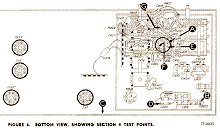
- Error in the parts placement diagram of 47-1230 service manual (52 KB)
- original 47-1230 schematics (25 KB)
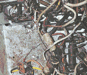
- Inside the chassis of my 47-1230 prior to alterations (188 KB)
- C419 in my 47-1230 with comments (190 KB)
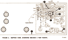
- How I believe it should be written. (52 KB)
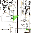
- thumbnail for error image (6 KB)
- thumbnail for schematics (7 KB)
- thumbnail for my 47-1230 (no comments) (14 KB)
- thumbnail for my 47-1230 (comments) (14 KB)
- thumbnail for my correction (6 KB)
To thank the Author because you find the post helpful or well done.
philco 47-1230

I am restoring a philco model 47-1230 and the wires from the electrodynamic speaker plug had broken loose. there are four wires green, white, red and orance and five holes on the female part of the plug that should connect to a four prong male plug attached to the speaker. The female plug has numbers (1-5) next to each hole....can someone tell me which color wire goes through which numbr hole for the four wires.....there are no diagrams etc that I have been able to find to assure proper connection...I know that this can probably be figured out with a meter but I just do not want to make a mistake....thanks for any help that I can receive.
To thank the Author because you find the post helpful or well done.
