philips: 209U;Overvoltage.Have you an explanation?
philips: 209U;Overvoltage.Have you an explanation?

Dear Radio Friends,
I have one Philips 209U.
To avoid an overvoltage (from the original 220V) I try to add one resistor to drop de difference from 220V to the actual voltage 230-240V.
But when I made the sum of all heater chain, pilot lamp and the mains droppers to find the actual heaters circuit value I got only 207,5V.
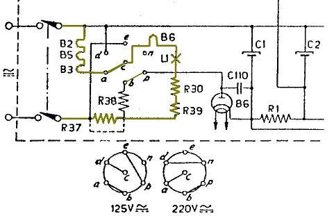
Heaters resistence:
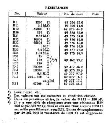
R37=75
R39=190
R30=170 Sum= 435 ohms
Heaters current: 0,1 Amp so,heaters voltage dropping is : 435x0,1= 43,5V
------------------------------------------------------------------------------------------
Tube heaters voltage:
UCH21= 20V
UCH21= 20V
UBL21 = 55V
UY1N = 50V Sum= 145V
-------------------------------------------------------------------------------
Pilot lamp: 19V
------------------------------------------------------------------------------------------- Sum of heaters circuit,pilot lamp and main droppers:145+43,5+19 = 207,5 V
-------------------------------------------------------------------------------------------
Well, did I forget anything?
Do You know anything that helps me to understand why the final value is not 220V?
Thank You for your time
Best regards
Mário
Ps: Resistors Table is below
To thank the Author because you find the post helpful or well done.

every electrical device is rated for specific input Voltage, lets say 220 V + or - 10%. Within this range, the radio works fine, and no part of the radio is stressed and working outside the Specification.
With tubes heating is critical in that way, that slight overheating is uncritical, while significant underheating is more critical.
Therefore it makes sense to me, to design the heater circiut in that way, that underheating is prevented ( in 220 V +- 10 % ( 200 V - 242 V )) Within that Range the Heating Current of 100 mA is between 97 mA and 115mA.
If it was my radio, i would not change anything.
Best Regards,
Henning
To thank the Author because you find the post helpful or well done.

I think, your forgot to take into account the anode/rectifier current through resistor R37 (cont. R38-b/p-B6 etc) in operation. You are caculating the tube`s operational values, not in cold condition. The tube heaters have different (lower) resistance in cold, compared to heated operation. It means, if you turn on the radio, the current is bigger (without rectifier current through R38), after the heater are in operational condition everything is.O.K. I got rectifier current 0.167A, it means for 230V supply you have to change the 75Ohm resistor to 110Ohm about.
Gabriel
To thank the Author because you find the post helpful or well done.

right, the rectifier has to be taken into consideration. Since the DC current equals the effective value (half wave rectifying is hard to measure and would need a true RMS Ammeter) You can assume ca 60 to 70 mA DC (+B) plus 100 mA RMS (filaments) through 435 ohms = ca 70 to 74 volts.
By the way, it is not the overvoltage one has to fear. Did You measure the filament (only) current?
KoBi
To thank the Author because you find the post helpful or well done.
Yes, but it It glows too much
Hi. Mr. Henning ,Gabriel and Konrad
Thank You for your prompt replies and explanations.
Yes You are right. I've to consider, 200mA in R37 after the rectifier begins to work. The resistor R37 drops more voltage when the current is higher. The sum is now 207, 5+7, 5= 215V.
I just verified that before the rectifier begins to work the current in heater circuit is approximately 200mA. Afterwards for 2 or 3 seconds it goes down to 0,1Amp. At the beginning the pilot lamp glows very very much, but after that it stands well.But I had already changed R30 from 170 ohms to 400 ohms.
The final value of heater circuit is 0,1A. It is OK. Pity is that 2 seconds flash for its life time.
We know that there are a direct relationship between the overloading and life time. In my sum (corrected) 215V correspond to 2150 ohms (calculated to 100mA current).
My set if connected to 220V the heaters circuit current is 100 mA. OK I agree it is not too much.
But, actually the mains voltage supply in Europe may be 230 +10% - 6% http://users.metro2000.net/~purwinc/seec2_2.htm
It means that there are a great probability to overpass 11V up the maximum permitted by the manufacturer (253- 242).
And then 253V:2150= 0, 1176 mA (higher than 115mA).
Well, but I've to calculate again the new drop value for R37 :-) .
It is ok on the edge.
PS: The resistors values indicated are measured in hot conditions. See in 3) of the Table (le valeurs ont été mesurées en condition chaude).
Thank You
Best Regards
Mário
To thank the Author because you find the post helpful or well done.
R30
The arrow show the resistor R30.
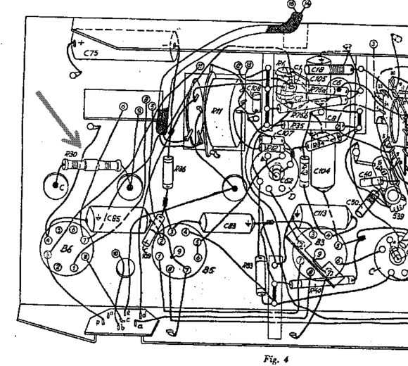
That's the one I found here damaged. I got no an equal to replace it. That's why I replace it by another. Then I decided that a 400 ohms resistor should be safer.
Meanwhile I found in some papers that R30 was placed to protect the scale lamp. Can it be a Varistor (variable resistor)? It has a strange shape.
Mário
To thank the Author because you find the post helpful or well done.