rca: R17; Radiola 17
? rca: R17; Radiola 17
Hello Fellow Vintage Radio Friends
My question today has to do with the "ground" on the Radiola 17. As you know this radio came with a standard two-wire (silk-braided) power cord which feeds into the filter on power transformer array. It also had a separate "ground" wire on the other side of the chassis. I wish to convert to a vintage looking three-wire power cord with "ground" and my question relates to where I would affix the "ground" wire at the filter/transformer end. Can I simply attach it to the chassis somewhere? Is there a preferred or recommended place somewhere on the power transformer chassis or tube chassis? Surely, for safety reasons, this conversion has been done many times before, not only on Radiolas but on other radios of this vintage. Any advice will be greatly appreciated. I am a beginner and hence the rather low-level of my technical understanding on these simple issues. I can't seem to find anyone in my area who enjoys this same hobby.
Best regards,
- Bill in northern California
To thank the Author because you find the post helpful or well done.
3rd wire ground for antique radios with transformer

Bill,
A generally good practice is to connect the 3rd wire ground to the chassis on radios with a power transformer, and this one is no exception. As you can see on the schematic, the B- connection on both the power supply and main chassis is connected to the chassis, and serves as the common point for the circuitry. You can connect your 3rd wire to the power supply chassis, or to terminal 11 on the terminal strips that serve as connections between the two chassis.
Connecting a 3rd wire ground in this way can be a significant improvement in safety in case deteriorating insulation in the radio has caused the hot wire of the AC line to have a path to the chassis.
When you add such a ground, it can also be a good idea to add a fuse on the hot AC line wire. Use a value just a little larger than the current draw of the radio -- typically somewhere between 0.5 - 2 amps.
As I'm sure you're aware, this is not something to be done on radios that do not have a power transformer. If the circuitry in the radio is not isolated from the 120 VAC power by a power transformer, one should generally never connect a 3rd wire ground at all.
Best regards,
Tom
To thank the Author because you find the post helpful or well done.
Beware of Autotransformers
I don't know if any Zenith models have Autotransformers, But some Kolster Brandes 1950s mains only models do and many UK 1950s Battery sets with built-in mains supply.
In this case you can't add an Earth wire.
On the Portable models with Autotransformer or dropper only for AC/DC the power consumption is always 18W or less (50mA filament series chain + 10mA HT) so I have a Shaver Isolation transformer / wall plate as common in UK & Ireland which is rated 20W and has 110V and 220V sockets that take US, Europlug or old UK 5A 2 pin.
I have drilled a third dummy hole so an old UK 5A 3pin plug (still available new) is fitted to radio (most would have had this or the 2 pin version). Thus the cord fits in battery/cord compartment (the Modern UK/Ireland rectangular 3 pin 13A plug doesn't) and in use the radio is isolated.
In the US you could put a 110V 50W isolation transformer in a box with a mains rated socket of type incompatible with regular sockets and fit that type of plug to live chassis sets that might have dubious safety. In US a voltage doubler and "live" chassis is more likely than an autotransformer on a set than simply a dropper, hence AC only rather than AC/DC possible with 200V to 250V mains.
To thank the Author because you find the post helpful or well done.
Mains connection

Hallo Bill, there is an issue with two or three wire mains leads to connect an antique radio.
Here in Switzerland (we have plugs Type J as found in the Wikipedia Mains plugs survey), we have three pronged plugs which can be inserted only in one direction in the socket, it is always clear, which of the three will be the "live" connector (which is marked in brown here in Switzerland), which is the "neutral" connector (color code blue) and which is earth (the middle one, coded green - yellow).
There are some devices with Type C connectors, nowadays only devices with double insulation - you can get the plug in in both directions, so "live" and "neutral" can be interchanged easily. The complete cabinet must have no metallic parts connected somehow to the innards.
With my sets in Switzerland (I collect commercial receiving equipment), I usually connect a three wire power cable and make sure, that the "live" wire ist the one, that is opened by the on/off switch, the earth wire can go to chassis / earth point.
Situation in England with their G Type plugs is very similar.
In Germany, situation is completely different: They have had the "Schuko" plug Type F (Schuko means protection contact, which is earth) which is two pronged and has the earth connector outside, on the metal strips that make contact at the outside of the socket. When it was invented, it was a good solution to have earth on a socket - but there is a big problem that the plug can be inserted both ways round.
So both connectors can have "live" or "neutral" potential, just depending from luck, how you plug it in... If the power switch opens only one of the wires, you can have the dangerous "live" potential on the mains transformer connectors even when the set ist switched off, the "neutral" wire is the one, which is opened by the mains switch.
There are some collector in Germany who have marked the "live" connector an the sockes in their shack and have marked all Schuko plugs, to insert them always in the same direction, to have the "live" potential led through the mains switch.
As I could see in Wikipedia, in the USA you can find the two pin plug Type A, which is interchangeable in the older form, it could be inserted in both ways so you have "live" on one or the other wire as by chance - there is the newer form of the two pin / blade plug in which the "live" connector is narrower and the plug can only be inserted in one direction.
Wikipedia told me, that today the three pin plug Type B which has a third earth connector is standard. This seems to be "unidirectional", the plug can only be inserted in one direction.
I do not know, whether the "live" wire is always in the some position in the upper two - probably it will be. I'm sure, one of our american friends will know.
If this is the case - I would make absolutely sure, that the "life"wire is always the one which will lead to the mains switch (in case, this will only open one of the wires) and will be fed to the power transformer.
As Michael stated, you cannot absolutely rely on the fact, that the wiring is made in the correct way. So for me, it' s an absolute "must" to check your mains power sockets in your house / repair shack for correct wiring. It's an easy task with a neon bulb screwdriver test light, in Wikipedia I have found, that in the U.S., there is even a electronic device which will indicate correct wiring of your sockets, indication life wire and also if the ground connection is insufficient or missing. So it might be worth to do this once in your life (or after moving house), to know about correct wiring of all mains sockets in your shack and be protected from electric hazard.
There is a good survey of the colour codes of mains wires also found at Wikipedia, colours are different in the U.S. then in Europe - useful when get a German made set.
As M. Watterson already stated, be very careful with sets without mains transformers. This can be the case with older German sets (Allstrom - because these can be run from AC and DC), but hardly ever with Swiss sets. These Allstrom radios and sets with autotransformers, I run only from a isolation transformer, I have a quite high power adjustable isolation transformer that serves me very will with U.S. as well as European sets.
Hope this helps Martin
To thank the Author because you find the post helpful or well done.
Additional hazard
I would make absolutely sure, that the "life"wire is always the one which will lead to the mains switch (in case, this will only open one of the wires)
Unfortunately on many UK models at least with chassis to one side of the mains the "on/off" switch is single pole and connects one mains wire direct to chassis!
Typical AC/DC PSU (more common on mains only ACDC sets)
Note that mains on/off is single pole from mains lead to chassis!
(The other pole is battery on/off)
The reason is to reduce "hum" pickup, especially when the mains switch is on the tone or volume control. This means that if the "neutral" is connecting to chassis and the "live" to HT Rail/Dropper/Autotransformer/Rectifier, the entire set can be live if it's off!
So always if in doubt about safety (too large gaps in rear cover, cover comes off easily with mains still connected, knobs that easily come off exposing metal work etc) use an isolation transformer that can only feed one set, either permenently connected in line or using a "mains rated plug" that doesn't fit domestic mains.
Unfortuneately you can't guarentee that every wall socket is wired correct polarity even with polarised mains plug, the live and neutral can be swapped and in systems where neutral isn't earth bonded at ingress to house, the neutral can be over 80V on 240V mains due to Earthing only at "substation"!
So ensure no loose knobs, bent rear covers, grub screw holes filled with wax etc. If the set is for an ordinary user without electrical knowledge or children / strangers may use it, then it may need an isolation transformer (can be in separate box so as not to spoil originality). Isolation transformers can't be shared to more than one set safely.
To thank the Author because you find the post helpful or well done.
How to recognize an autotransformer
Bill,
All of the above may seem a bit overwhelming to someone looking into this for the first time. On U.S. antique radios, most that have power transformers have "normal" transformers with isolated primary and secondary windings. On sets with normal power transformers, connecting the third wire ground to the chassis is a good choice. Your Radiola 17 has a normal power transformer, so you can go ahead and do that.
However, all of the above posters do point out important exceptions. One to beware of is a special type of power transformer called an "autotransformer." Autotransformers do not have isolated primary (where the power cord is connected) and secondary (where the radio's circuits are connected) windings, but rather use a single winding in the role of both primary and secondary.
If a schematic diagram is available (it is often just a single click away if you have found the model in Radiomuseum), you can learn to recognize the difference.
Autotransformers are in fact quite rare on U.S. antique radios. I've serviced and restored hundreds of them, and have only seen a few with autotransformers. The most common ones that use autotransformers are certain postwar Zenith radios. Here's the schematic diagram of the power supply of a Zenith G881, an AM/FM/phonograph set from 1950:

(source: Sams Photofact set 98 folder 16)
T1 is the power transformer. Note that it shows only a single coil, with various taps, some of which are connected to the power cord. This radio also happens to have a "hot" chassis, making it an unusually dangerous design. Connecting a 3rd wire ground to the chassis of this set requires great care and a decent understanding of many of things posted above, and a number of modifications. Most restorers would not use a 3rd wire ground on a set like this, but would use a polarized 2-prong plug, following the advice given by other posters above.
Fortunately, almost all U.S. antique radios with power transformers have isolated primary and secondary windings, such as what you see in this Silvertone 1311 power supply:

(source: Sams Photofact set 91 folder 11)
Although the Silvertone 1311 happens to be a guitar amplifier, its power supply is very typical of what you will find in antique tube radios with power transformers. Here you can see that the power cord connects to its own coil -- called the "primary" winding -- and the radio's circuitry connects to several "secondary" windings (almost always shown on the right side of the transformer diagram, with the primary on the left). Note also that the chassis ground is not connected to the power cord, but only to the isolated circuitry on the right.
If you have a radio with a power transformer like the Silvertone example here, it is generally beneficial from a safety point of view to connect the 3rd wire ground on the power cord to the chassis ground.
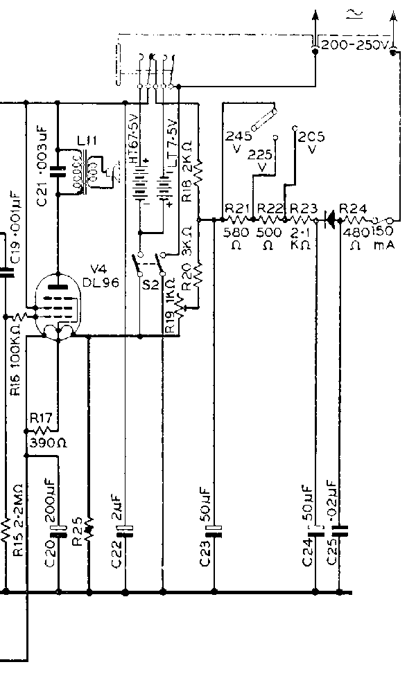
Older schematic diagrams like the one for your Radiola 17 may look a bit different. Here's the power supply for your set:

(source: Rider vol. 1)
Note that this early schematic shows the power cord and primary winding on the right, instead of the left. Nonetheless, it is clear that this is not an autotransformer -- the power cord is connected to its own isolated winding. So this set is safe to connect the 3rd wire ground to the chassis.
Sometimes there are capacitors from the power cord to chassis ground. Such capacitors should generally be replaced with modern AC rated capacitors (so-called "safety capacitors" are the best).
However, be aware that a very few U.S. radios -- particularly certain postwar Zeniths, but probably also a few others -- have autotransformers. Checking the schematic (or learning how to test for the difference once you understand it) can avoid situations where the sparks may fly or you create an unsafe situation.
And, as mentioned repeatedly above, this advice applies only to radios with power transformers. For sets without power transformers, you've got lots of good advice from others above.
To thank the Author because you find the post helpful or well done.
Thank you very much
Hello Thomas et. al.
Thank you all ... VERY much. Your combined replies have been very helpful on a question of central importance ... SAFETY! As stated in my original post I am learning as I go and it is essential for me, with no one around to show me how, to make sure that I am learning how do do things "the right way" ... I followed the wiring diagrams on the Radiola 17 and after cleaning out the chassis with an air compressor (full of bugs and cobwebs and dust) and cleaning all the contact points with isopropyl alcohol, the unit came up very clean. The wiring and insulation seems to be intact. I saw the ground wire and the antenna wire coming off the "On/Off" switch and I further observed another ground wire from the same tab on the "On/Off" switch running to the chassis. So, I performed no further work until reading your collective replies which confirmed my suspicions ... that it is o.k. to run the ground (or third wire) into the chassis VIA that same tab on the "On/Off" switch (after removing the old, rotten ground wire. The second tab on this same switch contains a remnant of an antenna wire so I understand now where and how the new antenna will be grounded ... I just have to find suitable material for a new antenna. The Radiola 17 manual says to try and avoid joints and soldering which introduces resistance to the antenna and degrades performance but I will almost certainly have to find some way of rigging-up an antenna socket to the new antenna wire. Modern connectors and soldering should help avoid resistance pitfalls (or at least, minimize them).
The information on AutoTransformers was scary. I'll be on the lookout for them if I handle any Zeniths. Thank you all for the warnings. I remember the European plug configurations from when I was a student in England. My old Ediswan (B.T.H.) "Power Pentode Two" has such a plug but I've had a step down transformer made for it to adapt it to USA mains power.
Are all of you aware that the RCA Radiola 17 has a line switch on the board with the UX 280 tube power transformer board? How interesting is that?
I don't understand how capacitance takes place in the Radiola 17 ... I don't recognize anything inside the chassis that looks like a paper or wax coated capacitor. Do I have to discharge capacitors inside the Radiola?
Thank you again, everyone
To thank the Author because you find the post helpful or well done.
Capacitors, antenna, and ground in Radiola 17
Hi Bill,
Careful! The antenna and ground most definitely do not connect to the on/off switch. Doing so would result in one of the more dangerous things you could do with antenna and ground connections (your antenna might end up connected to the hot wire of the AC line, posing an electrocution hazard if someone touches the wire).
Most likely you didn't really mean what you said. The antenna and ground connections actually go to the volume control. If the wires are crumbling, you may want to replace those wires. In any case, if you don't, just make sure they cannot come into contact with other wiring in the radio.
I would not worry too much about splices and connections on the antenna wire. If the wire runs outdoors, weathering might result in a poor connection, but for an indoor antenna wire, you will not generally have problems with splices or connections, as long as the wire is clean and shiny at the point of connection. If it is heavily oxidized due to age, scrape it a bit with a knife blade to shine it up before splicing.
There are two banks of capacitors in your Radiola 17. On the power supply chassis, one of the large metal boxes on top of the chassis contains 6 capacitors serving as power supply filter capacitors. A description of this is shown in page 20 of the manual you can download from the model page. While it is quite common for these capacitors to still be functional (as opposed to electrolytic power supply capacitors in slightly newer radios), it's a good idea to replace them. These are very old paper capacitors which can short out, possibly damaging the rectifier tube and the power transformer (maybe producing a bit of smoke in the process!). The two 3.5 uF capacitors should be replaced with modern 350 or 450 volt electrolytic capacitors. The closest (easy to find) modern value is typically 4.7 or 5 uF, which is fine. The + side of the electrolytic capacitors goes toward the connection to the 280 tube, the - sides go toward the connections to the filter "reactor" (or choke, in modern terms). The other capacitors in this power supply filter capacitor unit can be replaced with 160 volt (or anything larger) capacitors. You may not be able to find such small values for electrolytics -- using 4.7 or 5 uF will be fine for all of these. For the polarity, see the diagram in Figure 18 on page 21 of the manual. The "top" side on the diagram for each capacitor is the + side.
On the radio chassis, the "bypass" capacitors are rectangular metal boxes under the chassis, as shown in Figure 21 on page 25 of the manual. Offhand I do not see the value of these capacitors in the service information (it is probably there somewhere). In any case, using modern 0.1 uF 630 volt tubular capacitors (either polyester film or polypropylene) will be fine to replace these. Like the power supply filter capacitors, these are paper capacitors, which would be good to replace, since paper capacitors this old sometimes short and can cause damage. First priority, however, would be the power supply filters -- the capacitors on the radio chassis can be lower priority.
The manual you can download from the model page is especially detailed and helpful for this model radio, so I would encourage you to study it carefully. It has wonderfully detailed wiring diagrams and explanations that may be useful. Naturally questions may arise if you get into the circuitry to work on capacitor replacement, etc. Don't hesitate to ask more questions here.
The switch inside on the power supply unit is for selecting the line voltage -- 110 or 120 volts AC. You'll want to set that to 120 volts. The radio will work on the 110 volt setting as well, but voltages inside the radio will run a little higher, which stresses the old parts more than running things on the 120 volt setting.
The power supply of this radio is designed in such a way that the capacitor charge is automatically bled off by a resistor in the power supply. Provided that resistor is still good, you don't have to worry about charge in this radio after you turn it off and unplug it. If you have reason to doubt the integrity of the resistors in the power supply, another way to insure the capacitors are discharged after unplugging is to use a wire to short from terminal 11 (ground) to each of the other terminals (one at a time) on the terminal strip connections between the two chassis. After grounding each of these terminals, there should be no remaining charge.
To thank the Author because you find the post helpful or well done.
Yes, you are correct
Hello Thomas
Yes, you are quite correct ... it is the volume control and not the "On/Off" switch ... I misspoke and incorrectly identified the switch ... it is the volume control ... the chassis was upside down and I mixed things up in my mind ... seems to be happening a lot lately. ;-)
Thank you for the quick "heads up" and safety warning. Also, thank you for the information on the Radiola 17 capacitors ... I'm going to "find" them today and print out your reply and use it as a guide ... I think I will replace them as soon as I do some more studying and planning. I replaced capacitors in a 1952 Sentinel radio that I am practicing on. I made a capacitor discharge tool from plans I found on the internet. Looks like I won't need it on the Radiola 17.
I received the new braided three-wire power cord today so I am going to proceed with a ground wire from the volume control to the ground wire of the three-wire power cord and get that part of it cleaned up. I am becoming fairly proficient with soldering techniques and clean up and use of insulating heat shrink wrap. I am proceeding slowly and carefully, step-by-step and RMorg has been a wonderful resource.
I still need to figure out what to do about rigging up a "test" antenna ... it would be nice to have something set up here permanently in the shop that can be used for a variety of radio projects.
To thank the Author because you find the post helpful or well done.