Repairing old potentiometers
Repairing old potentiometers

The substitution of original components when restoring old radio sets is always an unpleasant measure justified only by the goal of achieving proper working conditions. In the case of potentiometers it is not difficult to find modern components with suitable characteristics at the price of a clearly different look but, in some cases, mechanical constraints don’t allow these replacements so that repairing the original potentiometers becomes mandatory. Of course before taking this option it could be rewarding to check whether among the 10468 pots available from Gary Schneider at “Play Things of Past” you can find the exact replacement for your set (quite possible if you are restoring an American set); if this is not the case you can try a repair. The first operation consists in carefully opening the potentiometer case in order to establish the construction technology; leaving wire-wound pots to the second part of this note, the resistive element of many pots constructed in the 30s consisted in a circular frame painted with a very thin resistive varnish that could not withstand the mechanical stress caused by a moving slider. The contact was thus obtained by pressing on the resistive surface a thin metal layer by means of an isolated pin inserted on the slider as shown in Figure 1.

Figure 1 - A 1936 resistive paint potentiometer
This technique was very effective and, usually, these potentiometers are still perfectly efficient; their worst enemy is the solvent contained in some contact cleaners that can irreversibly wipe out the resistive paint. The second class of potentiometers that can be found is given by pots quite similar to present-day ones where the resistive surface is in direct contact with a wiper mounted on the slider; in the example shown in Figure 2 the wiper is constructed with a group of spring wires. The arrows indicate the rivets to be removed to free the resistive element. This operation requires some care to avoid damages; I would recommend to mill slightly the top of the rivets (usually made with aluminum), to drill a small hole (no more than 2 mm of diameter) and to enlarge it by means of a very fine file until the complete elimination of the rivet. This avoids the application of excessive torques that could lead to mechanical damages in the resistive element.

Figure 2 - Direct wiper potentiometer
If your potentiometer is of the first type and the resistive paint has been wiped away, the only practical possibility consists in substituting the whole resistive element since resistive paints cannot be easily found on the market and, in any case, it would be almost impossible to distribute it in order to obtain, for instance, a logarithmic curve. The difficulties of the substitution can range from modest to substantial, depending essentially on the way adopted in mounting the resistive element; removing a glued element, for example, could require a delicate milling. Of course it is also necessary to prepare a geometrically compatible new element to be mounted in place of the old one and this means sacrificing another efficient old pot (modern ones are invariably too small) that could also be of the second type. Restoring a potentiometer of the second type will, of course, require a resistive element removed from a pot of the same type.
As an example, Figure 3 shows the original resistive element of a potentiometer mounted on a 1936 radio that is compared, in Figure 4, with the smaller new element obtained from another pot; in this case the operation was facilitated by the fact that neither of them was glued to the case.

Figure 3 - The internal components of a pot to be repaired

Figure 4 - New (left) and old (right) components
The different dimensions required, however, the extension of conductive paths and this was done by means of silver conducting paint (Figure 5).

Figure 5 - Label of the Electrolube ERSCP03B silver paint
Figure 6 shows the restored pot; it can be noted that some epoxy resin has been used to enhance the overall robustness.

Figure 6 - The restored potentiometer
Wire-wound potentiometers mounted on old radios have the typical look shown in Figure 7 and can be repaired in a comparatively easy way.

Figure 7 - A typical wire-wound pot of the 30s
Once that the cover has been removed, determine the exact point where the interruption is present and mark it accurately. Remove then the central axis connected with the slider and use a very fine sandpaper (P1000 or even finer) to bare the wire along a vertical band with a width of 3-4 mm centered on the interruption point; clean carefully using compressed air.

Figure 8 - What is needed for repairing a wire-wound pot
Use then a very small brush to distribute silver conductive paint on the cleaned band as shown in Figure 9.

Figure 9 - The restored winding
Check the continuity, perform a two hour test at a current compatible with its rated power and remount the potentiometer. The silver conductive paint Electrolube ERSCP03B can be found on the RS catalogue (code 101-5621); it is expensive but very effective. Similar products can be found on the automotive market for repairing the connections of rear window defrosters and are equally effective. Its use for repairing wire-wound potentiometers has been a precious advice by Leonardo Mureddu, the creator of the impressive site “Le Radio di Sophie”. An alternative technique for restoring wire-wound pots consists in inserting a small metal band between the wire winding and the potentiometer case; I would not recommend it because it can create further damages and, even when successful, suffers from reliability problems.
To thank the Author because you find the post helpful or well done.
Log potentiometers and their replacement

Yes, this is a difficult repair of considerable effort, due to the required accuracy and to the small size of the parts, but several times we have had to rebuild broken shafts, worn brushes or resistive elements. Whenever possible, I prefer to replace old pots with carbon composition types, Allen Bradley type J or similar, for their superior performances and low noise. Unfortunately today the availability of log or antilog potentiometers is quite poor and the linear types are not suitable for use in volume control circuits.
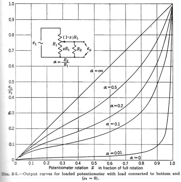
As usual, a solution can be find in the old literature, based upon the resistive loading of linear potentiometers. If we put a load resistor from the cursor to one end of a linear potentiometer, we have a non-linear voltage variation at the output. Depending upon the side where the load is connected, we have quadratic curves, which approach enough either antilog or log ones. Here are plotted the output curves for both configurations, assuming that the circuits are driven by a voltage generator:
 |
 |
As we can see in both cases, the middle curves approximate the typical curves of antilog and log potentiometers. Linear potentiometers over 1 megaohm, required to have the best fitted curves, are usually available at affordable prices, coming from inventories of old television shops. In many cases the error due to the resistance of the source is relatively low and can be ignored.
Reference: Electronic Instruments, MIT Radiation Lab Series, Vol. 21, section 5-4, ‘Curve fitting with linear potentiometers’.
To thank the Author because you find the post helpful or well done.
crude pot repair
Both the volume and tone controls on two 1946 Sentinel A.M. radios I restored recently were annoyingly scratchy. Being a tyro at this hobby, and not having read these posts, I approached the problem in a different – some would say “crude” – manner.
I drilled, ever so slowly and carefully, into the Bakelite (?) body of the pots with a sharp bit just slightly larger than the spray nozzle on a Deoxit D-100 spray can. After a few spritzes, it worked. The scratchiness disappeared on all four pots. As you can see in the photos, there is some sort of a paper lining on the interior walls of the bodies of the pots. If tiny bits of Bakelite and paper entered the bodies during the drilling they seem not to have affected anything.
Attachments:
- volume pot (119 KB)
- tone pot (119 KB)
To thank the Author because you find the post helpful or well done.
Another crude pot repair
All I have read is valid but an old method I have used to overcome scratchy pots when their style or design meant they could not be easily replaced and were bad that electronic spray had limited lasting effect was to use Vaseline, now I am sure there is modern track greases.
As a retired TV service engineer during the age of rotary then slider controls, many multi tv sliders came on a plastic form with front scales but open track backs these would become contaminated with toxins in the air plus some sliders never moved often only to cause havoc when moved!
Spray lubricants helped but would happily attack some plastics or make the slide action "gritty", gentle clean of track and slide parts followed by smearing Vaseline on these areas sealed (from contamination) and lubricated in one, losing only a few who could not be fixed this way. Another problem with spray lubricants to be aware of is pots with mains switches these have had time to carbonize a bit and can become integrated with over spray oil reaching them through the switch lever, this can fester, arc then burn more so on paxolin type switch forms. On these (with mains switch pots) I would not spray but remove the track top (if possible) and Vaseline it or be forced to change where possible
The best spray lubricant I had used was a Philips version which had a thicker oil/lubricant while others could cause a worse reaction but fine on switches, an old engineer I worked with loved his Carbon-tet' came in tins from RS which he spashed on Bush/Murphy dual standard TV's switch then other engineers watched with humour as its vapour ignited during a switch flash!
Hope this of some help
To thank the Author because you find the post helpful or well done.
Potentionmeter cleaning and lubrication
Very nice article which is certainly helpful. If the resistive film is not destroyed e.g. due to the mechanical stress by sliding, my experience showed that the following procedure helped in many cases. First spraying WD40 detergent into the pot. Let it work by turning the pot minimum 20 times from end to end.
After drying of the WD40 I use the gun oil Ballistol as final treatment.
After trying everything available from various Kontakt 6xx products to simple alcohol and including DeOxit (rather expensive but good) for me this worked out to be a cost efficient method. Ballistol lubricates and helps to have a long lasting performance of the pot.
My field of restoration is old test and measuring equipment, tube stereo gear including recording studio amplifiers, musical instruments amplifiers for guitar and bass, and of course last not least occasionally old tube radios plus portable transistor radios.
To thank the Author because you find the post helpful or well done.
german radios controls
Hello,
I am often repairing german radios which have volume and tone control in one . Often volume control is hard to turn and tone control does not move at all. Those controls are not available, they have to be repaired.
The only way to repair it is to heat up the tone control shaft with high power hot iron ( I use 350 Watts solder gun) and special wooden knob I made for this purpose- original plastic knob would melt.
As the tone control shaft heats up, it will start to get loose and turn, the old hardened lubricant melts, I keep turning it until gets loose and at the same time insert syringe between shafts with good quality machine oil.
After it cools down, Deoxit will clean it to perfection.
Try it, it works, Tony at www radiodoctor.org
To thank the Author because you find the post helpful or well done.
Resistive film reconstruction
Restoring old sets requires levels of respect for the original components much more restrictive than in simple repairing so that recovering old components instead of substituting them with modern ones is, when possible, mandatory. Some potentiometers constructed in the 30s did not rely on the direct contact of the wiper with the conductive film but pressed a flexible metal layer on the film that was so delicate that it would be destroyed by most present-day contact cleaners. Another critical aspect of these potentiometers concerns logarithmic types whose conductive film was, in some cases, obtained using two different resistive paints with the consequence of possible fractures in the transition area. The effects of the resulting random discontinuities in the resistance values in certain positions of the potentiometer can be particularly relevant when the potentiometer is directly inserted in the polarization circuit of a tube like in the example, concerning the IRRADIO DL594, reported in Figure 1.
Figure 1 – Volume control in the IRRADIO DL594
Situations like that indicated by the red arrows in Figure 2 can be treated by using a silver conductive paint like the Electrolube ERSCP03B or similar products.

Figure 2 – Interruption and lacking zone in the resistive film
The application is, from a practical point of view, a bit more difficult than desirable and could take advantage of the use of the inexpensive magnifying glasses available for performing precision mechanical operations. It can be worth also applying some conductive paint on the rivets that assure the connection of the resistive element (yellow rows in Figure 2).

Figure 3 – Restored continuity of the resistive film
A good tool for applying the silver paint could be a sharp toothpick (leaving the paint drain along its side) or, of course, a very sharp small brush; in any case the control of the paint viscosity is very important and could require adding a very small quantity of nitrocellulose solvent to the paint.
To thank the Author because you find the post helpful or well done.
Complete reconstruction of the resistive track in worn pots
Repairing old sets offers many degrees of freedom not available in restoring where the respect for the original design and components is a primary concern that calls for reconditioning instead than substituting worn components with modern ones. The large number of beautiful radios brutalized by substitutions based only on performance considerations certainly does not call for increasing their number; on the other hand it can be extremely difficult or even impossible to find original replacements for electromechanical components like potentiometers whose mechanical structure, in some cases, is integrated into more complex and specific environments.
A suggestion proposed in a previous note concerned the substitution of the resistive substrate with a dimensionally and electrically compatible one extracted from a similar device; this approach has been successfully followed but it can be difficult to find the substrate to be transplanted while the substitution of the whole potentiometer with a new one built in the same period can be almost impossible because of mechanical constraints. An example of a situation of this kind is reported in Figure 1 that shows the potentiometer used in some Magnadyne radios endowed with the Duotonal control that relied on a single knob operating simultaneously on a traditional tone control and on the selectivity by modifying the distance between windings in the first I.F. transformer.

Figure 1 – A Magnadyne Duotonal control potentiometer; the total length of the axis is 30 cm.
The potentiometer shown in Figure 1 is beautifully designed and realized; it can be completely disassembled, taking apart also the resistive track, and reassembled at will without removing any rivet; moreover the rotating slider does not act directly on the resistive track but presses a polished flat ring on it in order to minimize wear. Unfortunately the resistive track is completely wiped out by solvent-based contact cleaners and increases substantially its value (even 100 times) when treated with traditional noise-reduction products.
The easy substitution of the resistive substrate and the absence of a direct contact with the rotating slider suggested trying a complete reconstruction of this element and this required solving two problems, namely finding a suitable material for the substrate and a suitable resistive paint applicable without specific equipment. The search for resistive paints endowed with the high surface resistance necessary to construct potentiometers in the MΩ range did not lead to positive results; the only easily available product was GRAPHIT 33 by Kontakt Chemie, whose surface resistance is in the range of 1-2 KΩ and looks thus suitable only for realizing potentiometers in the 5-10 KΩ range. It was, however, decided to test anyway GRAPHIT 33 under various dilutions.

Figure 2 – The excellent GRAPHIT 33 by Kontakt Chemie
To carry out some tests it was still necessary to select a suitable material for the substrate and to construct a test bed for checking the electrical and wear-resistance capabilities of the solutions. The selected material has been polycarbonate that is commonly used in serigraphy; the sheet that has been used had a thickness of 0.25 mm, one of the sides was matt while the other was polished (Figure 3).

Figure 3 – A sheet of 0.25 mm polycarbonate
A test bed was then constructed by removing the resistive substrate in an old potentiometer where the polycarbonate resistive tracks under test were kept in place by two small screws that substituted the originally used rivets. The selected potentiometer was endowed with a direct contact slider useful for expediting life evaluation tests (Figure 4).

Figure 4 – The test bed for the resistive tracks
Some resistive tracks (like the coarse one that can be seen in Figure 4) have then been constructed by applying one or two layers of GRAPHIT 33 on the matt side of the substrate. The resistance values were the expected ones (under 20 KΩ); the surprise concerned, on the contrary, the number of cycles that the potentiometer could withstand without showing significant resistance variations. In fact, the resistance shows a decrease of approximately 10-12% during the first 1000 rotations then stabilizes. This unexpected result is probably due to the excellent lubricating properties of graphite. The subsequent tests concerned the application of GRAPHIT 33 diluted with nitrocellulose solvent. The correct procedure is summarized in Figure 5; first non diluted GRAPHIT 33 is applied in the lower area of the resistive track (in order to reach a very low resistance value at the extremes of the rotation) then the diluted mix is applied, with a small brush, to the remaining area.

Figure 5 – Preparation of the resistive track
Getting (almost) exactly the desired value requires, usually, some trials that, however, do not require cutting a new substrate. A good technique for increasing the resistance value consists in applying, over an already prepared substrate, a small drop of solvent in order to absorb, by means of the brush, part of the graphite. Several thousand cycles do not alter the resistance also in 2 MΩ potentiometers (the maximal value that I have realized).

Figure 6 – The restored potentiometer of a Magnadyne SV13
Despite the excellent results that can be obtained by applying the technique described above, it is necessary to use the following precautions:
1) Avoid using any solvent or solvent-based contact cleaner on the resistive track. It would be destructive.
2) Avoid as well using noise-reductions products. The potentiometers obtained in this way are not noisy at all and traditional noise-reduction products will increase in an uncontrollable way their resistance (exactly as happens with the resistive track of some old potentiometers).
3) Avoid inserting potentiometers obtained in this way in circuits where a significant current is present.
To thank the Author because you find the post helpful or well done.
Restoring the resistive track in a 1930's pot
I would like to "second" everything that Roberto Guidorzi has said in the articles above. It is sometimes possible to restore a resistive element in a 1930's potentiometer using conductive paint, and in my case it turned out to be rather easy.
In repairing a 1934 Philco 84B radio, I encountered a faulty potentiometer of the type described by Roberto in his first article above. It was a 20k pot on the antenna input that controls the volume and also includes the on/off switch. I had fixed many dirty or intermittant potentiometers before by simply spraying some contact cleaner into the mechanism. These potentiometers had included a solid graphic ring of some kind that was not affected by the spray. I guess I had been lucky in the past not to encounter a potentiometer of this type. The contact cleaning spray worked just fine on the on/off switch, once I had removed it from the pot. But just as Roberto describes, my quick spray completely removed the conductive paint. The resistive element was now just a ring of pressed fiberous material.
I ordered a couple of replacement pots that seemed promising. But then I decided I had nothing to lose by trying to restore the original one with some conductive paint. (I had not yet read Roberto's articles). I had a jar of MG Chemicals "Total Ground" on hand, which is a carbon print conductive paint. I painted a strip on some paper, and was surprised to see the resistance was 5k for about a centimeter length, 2 mm width. That seemed about right, so I dipped a brush into the paint, thinned it with a couple of drops of acetone, and painted it onto the substrate ring. The absorbant substrate was raised and naturally attracted the paint, so it was easy to paint just the right area. When it dried, the total resistance was about 15K. Some very gentle rubbing with fine sandpaper and cleaning of some excess paint along the edge quicly brought it up to 20k. I was amazed at how flat and smooth the top surface was. The contact element had no trouble sliding over it. And there was no need to remove the rivets. For values above about 50k, I would assume that some careful pre-thinning of the paint with a solvent would be effective.
Here is the carbon paint I used (on Amazon): My experience agrees exactly with what Roberto has described. It really works - and in my case at least it was easy to do.
To thank the Author because you find the post helpful or well done.
Repairing old potentiometers

Sometimes it is impossible to find a correct potmeter replacement. In that case an option is to glue a PCB mount potmeter to the back. In my case I fixed the high tones potmeter of my Telefunken Concertino 8 this way. It worked quite well. Of course, it is not original, but I simply wanted the radio to work.


To thank the Author because you find the post helpful or well done.