SABA Freudenstadt 8
SABA Freudenstadt 8
This is my first post on this forum...
I´m restoring a SABA Freudenstadt 8. I have put up some pictures on my websait: http://hem.bredband.net/b101180/SABA%20Freudenstadt%208.html
The radio sounds great on UKV. The sound is excellent and crystal clear and it seems quite sensitive.
The only remaining problem to solve is the distorted sound on the Medium Wave Band. The radio seems quite sensitive but the signals I receive sounds like they are overloaded and not very pleasant to listen to. I have tried changing the tubes, but that did not help the matter.
Does anyone of you have any ideas of what might be the problem, and how to solve it?
/Håkan
To thank the Author because you find the post helpful or well done.

Hallo Håkan.
Welcome here
It looks, as if your radio would not have any AGC. Maybe the IF- Stage is overloadet.
.
To thank the Author because you find the post helpful or well done.
Hello Hans!
Thanks for taken an intrest in my little problem!
While receiving a strong station:
Messbuchsen R: 2 volt
Messbuchsen D: 25 volt
Between C45 and R27: 35 volt
/Håkan
just removed empty frame Martin
To thank the Author because you find the post helpful or well done.
Hallo Håkan.
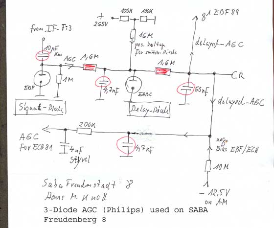
I see, i am on the right way! The ECH81 has no or verry low AGC Voltage.
Some condensors and resistors take part on this failure.
And maybe Tube 4 EABC80.Tomorro i post a Detailet Diagramm with instructions what postition is to observe.
hans
To thank the Author because you find the post helpful or well done.
Thanks Hans!
I do not think it is the EABC80. I have used two of them, both NOS-tubes.
Looking forward in hearing from you!
/Håkan
To thank the Author because you find the post helpful or well done.
Orders from Hans
Hallo Håkan.
To thank the Author because you find the post helpful or well done.
Thanks for your effort Hans!
First...
Between point R and ground I have 180 kiloohms.
I will check the specific components later today.
/Håkan
To thank the Author because you find the post helpful or well done.

Hallo Håkan
Allright.
It seems, there is a shorting to the ground left of R1 200 Kohms, .180 and 200 nearly the same.
Your 180 say that to mee, maybe???
Please look there. See new diagramm.V2
HANS
To thank the Author because you find the post helpful or well done.
I can not say that I have found what is wrong, but me poking around in the radio have resulted in that the resistance between messbuchse R and ground now is 2.57 Mohm.
May be the sound has improved a little bit...
/Håkan
To thank the Author because you find the post helpful or well done.
One observation...
Below the 10M resistor (that is between R65 and R68) there should be -12,5 volt on AM.
I have only 11 volts.
Is that significant?
/Håkan
To thank the Author because you find the post helpful or well done.
To thank the Author because you find the post helpful or well done.
Dear Hans,
I think I have found what was wrong. I remembered that I have read somewhere a while ago about the MF-filters and distortion.
After I replaced C31 and C32 in Fi.2 with NPO-capacitors everything is okay and the sound on Medium Wave is normal and clear. Obviously the old capacitors were (or had become with age) current dependent causing them in fact to "modulate" the signal in tune with the AGC-current.
I do not know, but did they not use to modulate the transmitters less than is the custom nowadays? Perhaps the radio was quite all right when it was produced, perhaps it is the "over-modulation" today that is causing the problem....
/Håkan
To thank the Author because you find the post helpful or well done.

Dear Hakan,
Congratulations for the successful repair. Nevertheless I think there is still a remaining fault in the AVC circuitry. The distortion may have gone, but the full performance is certainly not yet recovered.
H.Knoll has clearly analysed and depicted where and why the 2 Volts are not correct.
Being myself an experienced Engineer I am always amazed how thoughtful and skilled H.Knoll is going to assist.
I can understand Your pride, but between the lines one could also read "blame, You got the wrong track". And I could understand if he would lose his motivation. He has not deserved that, by no means.
I hope You may understand my open words. But I hate the idea to lose H.Knolls cooperation.
Regards,
KoBi
To thank the Author because you find the post helpful or well done.
I received a short message from Mr. Olsson

Here is the message from Mr. Olsson the language member admin received:
Please remove me from the membership list of Radiomuseum!
Regards,
Håkan Olsson
I naturally did immediately what he asks for. Such a reaction is typical for certain persons who never will be "growing"/prospering because of their wrong pride. They stay "halfsighted" and are not really desirable members.
Konrad did gratulate him for having found an other problem and told him where the real problem still lies if he measured such a low AGC voltage. He also told WHY his answer may lead many readers to the wrong conclusion that HMK was wrong, but Hans M. Knoll outlined very clearly the primary problem - with quite some research and personal work which enables many others to understand how the delayed AGC is coming to birth.
In post 12 Mr. Olsson looses his way which can only mean that he does not understand why the found problem has to be solved. This can happen. With his measures, which might also have been necessary in a second step, he has a working set which works much below it's possibilities and some parts will not be pleased to get such a lot of current, working strong stations. Mr. Olsson is not aware of this problem and blames the transmitters ;-)
He could have gone on and do those few measurements ... and post differently. He might have found out that HMK is one of the most gifted radio engineers who has electrically designed just such radios for more than two dacedes! We all can learn a lot from his outlinings he does, even struggeling in a foreign langauge to help somebody.
For the end I show you an example how a positive thread might occur. I don't know if members can understand how much work it is to go this way of methodically and professionally find the way to help.
To thank the Author because you find the post helpful or well done.

Thank you Hans, and thank you all for maintaining and contributing to this amazing site!
Even though, there might have been a communication issue from this new/past member, please archive this thread for future use.
Han's help and contribution is invaluable to this site!
Thank you Konrad and Ernest, for keeping clarity and civilty, more is learned on RMorg than any textbook out there that I've seen to date.
To thank the Author because you find the post helpful or well done.
Thanks to
To thank the Author because you find the post helpful or well done.
 Thread closed by a moderator. But replies can be made through a moderator.