schaub: How it works by John Hunt
schaub: How it works by John Hunt
Fellow Radiophiles,
I had a recent email exchange with John Hunt. He owns the well known web page about the Fremodyne super regenerative FM detector at http://cool386.tripod.com/fremodyne/fremodyne.html.
John sent me a very nice analysis of the operation of the Schaub Pirol 56GWU. The following is that analysis by John Hunt.
In an earlier email I had told John that the FM detector was super-regenerative. John has correctly shown otherwise. The difference is based on the frequencies involved and on the component values in the schematic, rather than on topology.
Enjoy,
-Joe
Hi Joe, Interesting to see the info on the Pirol; another of those cheap German sets of the 50's...but this is the first two valve set of its kind I've seen. I question the detector being superregenerative though.
There's an optimum ratio of quench to receiving frequency. As we can see the IF for the VHF part is 10.7MHz. That's pushing it a bit for a superregenerative detector. It's also why we almost never see superregenerative receivers for the MW broadcast band; the optimum quench would be quite audible.
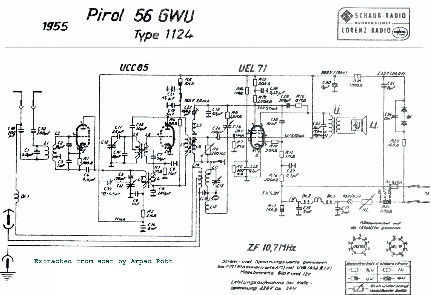
My interpretation of the Pirol circuit is this: Starting with the MW section because that's easy, L10 is the aerial primary winding, with a tapping low down for a long wire aerial. The top tapping makes use of the VHF transmission line for the MW aerial.
L11/C12 is the MW tuned circuit which feeds the UEL71 tetrode grid via grid leak C24/R7. Ignore L8 in the signal path; as it's a 10.7Mc coil it will have minimal effect on the MW signal passing through.
L12 is the regeneration feedback winding with C23 used to adjust the amount of regeneration.
The audio output is conventional with negative feedback/tone correction provided by C29 and R19.
Presumably, the volume control for MW is performed by C24, the regeneration control. An often used method, but not good because you lose selectivity as the "volume" is reduced.
All completely standard practice so far. Turning now to the VHF portion, the UCC85 (26V heater version of 6AQ8), first triode accepts the aerial input from L1/L2. This circuit is broadly resonant around the VHF broadcast band by means of C1. The low Q due to aerial loading will see to it that the bandwidth is broad enough for the whole band.
The first triode is operating as a neutralised RF amp, with C4 providing the antiphase feedback into the lower part of L2. Nothing unusual here.
L3 is the plate load for the RF amp and feeds the amplified VHF signal into the converter stage based around the second triode.
C12/C5/C37 tune the RF circuit with C37 being the trimmer to bring the RF circuit into correct tracking with the local oscillator.
The frequency converter which converts the VHF signal to 10.7Mc/s is also nothing unusual. It's a standard oscillator circuit.
The VHF is fed into the converter grid via C7 from L4. R3/C9 are the oscillator grid leak.
As this kind of oscillator requires both sides of the tuning condenser to be floating, they have got around this by coupling the tuning condenser by another isolated winding, L5, and can thus earth the moving plates.
L7/L8 is the 10.7Mc/s IF transformer. C11 is the padder capacitor to make the local oscillator run above the RF.
This time round, the 10.7Mc/s signal is fed to the detector triode by the same grid leak condenser as used for MW (C24), and the tetrode now operates like it did before but at 10.7Mc/s and not 550-1600KHz as it does on MW.
Regeneration feedback is provided by C22 preset (this can be preset because the frequency is now fixed), and L9 the feedback winding.
C19 is the RF bypass for both MW and 10.7Mc/s which is standard for any regenerative detector. However, bypassing is never perfect here and enough RF exists to provide regeneration by C22 (10.7Mc) or C24(MW).
R8 prevents the MW feedback circuit shunting away too much of the 10.7Mc/s signal given that C24 would shunt away too much at 10.7Mc/s. Presumably because of the more critical nature of C22's adjustment, R6 is provided for the FM volume control simply by progressively shorting out the IF signal.
As a by product of this, regeneration will also be reduced (because of loading L8, and thus L9) to further assist volume reduction. Now, as to C22's adjustment. If this is taken to the point just before oscillation like for AM, the bandwidth will be too narrow for the 75Kc/s deviation of FM. So it would appear that to set C22, R6 is set to full volume and C22 set to max capacitance just before distortion (from a narrowing of bandwidth) sets in.
This way, reducing R6 will only broaden bandwidth and to no ill effect.
So, in my opinion this set uses a regenerative detector for FM, and not a super regen one. The reasons being:
1)C24/R7 would give a quench of around 10Kc/s which is very audible,
2) there is no quench filtering between the detector plate and audio output stage,
3)10.7Mc/s is rather low for efficient superregenerative operation.
I would expect the performance of this receiver on MW to be like any other two valve set; good loudspeaker volume on all local stations.
For VHF, my guess is would be like a straight VHF regenerative set but with a little more gain. It would bring in local stations OK but not a DX set.
I did have a Telefunken Rhythmus 52GW which had an untuned RF stage and one IF amplifier...my version was the later one that had a ratio detector instead of the slope detector. Sensitivity was poor. It would bring in the main Sydney stations 80km away but really needed the outdoor aerial to do so properly.
In fact, I could easily find out what the Pirol would be like as it just so happens I have a prefabricated tuning head from a Sansui tuner/amp. It uses two 6CW4's for the RF and a 6AQ8 for the converter. Just have to feed the IF o/p into a grid leak detector and provide a bit of feedback.
There is a book I recommend you try to get "Superregenerative Receivers" by J.R. Whitehead and printed by the Cambridge University Press. There are portions viewable on Google Books if you want to look it up. Any in depth analysis of SR Rx's unfortunately requires lots of maths.
All the best for the New Year,
John
To thank the Author because you find the post helpful or well done.
More from Germany

Hello Joe.
When you or Mr Hunt have an interest in more of the technique of superregenerative circuits,
see this model.
http://www.radiomuseum.org/r/telefunken_capriccio_50ukw.html
It uses an IF of 20,7 Mcs., and as a demodulator, an Audion in superregenrative circuit.
This was the one and only Model in Germany with a "Pendler" as Demodulator.
I know this Radio for many Yeahrs, and from now on, also you know this Model and it's Secret. Nobody else do that.
I with you all the best for 2010
Hans
To thank the Author because you find the post helpful or well done.

