siemens: E9 ; Standardsuper: FM Ant button
siemens: E9 ; Standardsuper: FM Ant button
The FM dipole is only going to pickup "E" field on MW & LW. I have read people suggesting that the FM ant switch is to "improve" AM reception. Well it does.
But not by picking up more signal from the Radio station. The Ferrite Rod is the main aerial for AM bands. The E field is very much higher at Lower frequency when it's a very short aerial in the "Near Field", this means the FM dipole will pick up very local interfence from SMPSU very well but the AM radio station will be poor reception on it.
Thus by rotation of the Ferrite Rod and trying both orientations of the dipole (to reverse phase) the local interference can be greatly reduced with perhaps just a small reduction in the desired signal. The local SMPSU Interference is greatly reduced. Presumably in 1959 the local interference would have been TV line Drive harmonics of 15.625KHz in Germany and any local motors like a fridge compressor.
To thank the Author because you find the post helpful or well done.
siemens: E9 ; Standardsuper: FM Ant button

I have s problem with the WUK or FM wave band for this Siemens E9 tube radio. It produces a lound cracking noises as I keep dialing through different stations! Volume goes up and down. Any idea how to fix this problem. I am amature/beginner in this area of tbe radio but I can replace capacitor if I know how and where to find it. Long and Medium Waves are working fine.
Thanks for your help
Ali
To thank the Author because you find the post helpful or well done.
siemens: E9 ; Standardsuper: FM Ant button
See the Electrolytic capacitor on the FM discriminator, it's 2uF between pin 2 & pin 7 on the EABC80.
Replacement is 2.2uF or 3.3uF at 12V to 25V rating is fine, the value isn't critical. Use a new part. Observe polarity, + to pin 7.
The EABC80 could be faulty, but the more likely scenario is the capacitor.
To thank the Author because you find the post helpful or well done.
siemens: E9 ; Standardsuper: FM Ant button
Thanks so much for the quick response. Will try to fix it as per your instructions.
Ali
To thank the Author because you find the post helpful or well done.
siemens: E9 ; Standardsuper: FM Ant button
Hi Mike,
Thanks again for sending me the information regarding repacing the electrolytic capacitor for my Siemens Superstandard E9 with value of 2.2uF located between pin 2 and pin 7 on the EABC80. I received the a new capacitor replecement today (3.3uF 50V). However, I could not fine the 2.2 old capacitor that needs to be replaced. I wonder if it is the white oval shape with brown paper sticking out out of it as in the following pictures foucing on EABC80 pins and related sorround capacitors and resistors.
Thanks so much
Ali
Attachments:- EABC80 related Capacitors (133 KB)
- EABC80 related Capacitors (133 KB)
- EABC80 related Capacitors (97 KB)
To thank the Author because you find the post helpful or well done.
siemens: E9 ; Standardsuper: FM Ant button
some more photos
Attachments:- EABC80 related Capacitors (102 KB)
- EABC80 related Capacitors (131 KB)
- EABC80 related Capacitors (131 KB)
To thank the Author because you find the post helpful or well done.
siemens: E9 ; Finding the discriminator electrolytic cap.
It will be round and one end will be marked +
Likely also marked -20 ... + 80%
With set off & disconnected from mains, find the polarised capacitor connected to pin 2 and pin 7 on the EABC80, it may not be right at it. Use the DVM / DMM on 200 or lowest ranges, or beeper mode to trace the wiring.
It's most likely to have an aluminium case with + end only insulated. Perhaps printed on case and a clear label, or else a printed label that might have come off.
Mine is in the attic someplace.
To thank the Author because you find the post helpful or well done.
siemens: E9 ; Finding the discriminator electrolytic cap.
Hi Mike,
Again thanks so much for the prompt response. As you can tell, my tube radio knowledge is pretty basic but I am doing a lot reading and research trying to learn as much as I can. I am actually a Ph.D. chemist working at the Food and Drug Administration (FDA) federal government at the
This Siemens StandardSuper E-9 radio (photo attached) was sent to me by my brother who lives in
I will follow your instructions reagrding fixing this radio and update you, hopefully, with the good news! Sorry if I bored you with my long e-mail.
Best wishes
Ali
.
Attachments:To thank the Author because you find the post helpful or well done.
siemens: E9 ; Finding the discriminator electrolytic cap.
I got mine down from the attic.
The 2uF is actually soldered between earth and pin 9 on the EF89 (g3, screen grid). That point does connect to the EABC80 detector.
It's at the edge of one of your photos.
Sometimes a "no connection" pin on a valve base is used as a tag, very confusing, but in this case it will be something to do with interstation muting, as you can do limited gain control on g3 of a pentode. I'd not noticed such a technique before.
My E9 has a poor condition case and broken scale glass. I've hidden the breaks with card as they are at the two ends. I also have a series dropper resistor fitted as these sets don't have a 230V setting. The EU uses an imaginary 220V, the UK has a tolerance that allows up to 245 (typically 240) and here, Ireland, is typically 230, though we seem to have a few volts more. It's a "nominal" 220V!. It's not a problem for modern SMPSUs or generous rated transformers with a linear regulator (Semiconductor only gear). Some transformers are tight specs, so may overload. Also lamps and Valve filaments can have 1/2 life at +10% over the correct rating. Having 6.1V is far better than 6.5V. Note that series "tube battery" sets using a 7.5V battery are actually supposed to have 6.8V on mains and the 1.5V filaments are really 1.4V and ideally run at 1.3V to 1.35V.
To thank the Author because you find the post helpful or well done.
siemens: E9 ; Finding the discriminator electrolytic cap.
Hi Mike,
I did replace the 2uF capacitor (button left hand corner in attached photo) with 3.3uF, 50Volts. The good news is it did improve slightly the sound quality and reception on Medium and Long Waves. The bad news is there is no change or improvement in the FM or as you guys call it UKW. The magic eye tries to come into focus when I move the dial along the stations/frequencies with the sound produces very high pitch cracking noise trying to find the stations. Also, there no is difference in the sound (volume or clarity) whether I insert the FM /UKW antenna at the back of the radio or not.
I am going on offical trip in the next few days and will be back next week.
P.S. I think if you work for pharmaceutical industry, you will get consultant fees!
Again, I would like to thank you so much for all your help and guidance.
Ali
Attachments:- EABC80 related Capacitors (30 KB)
- EABC80 related Capacitors (133 KB)
- EABC80 related Capacitors (133 KB)
To thank the Author because you find the post helpful or well done.
siemens: E9 ; Finding the discriminator electrolytic cap.
"replace the 2uF capacitor (button left hand corner in attached photo) with 3.3uF, 50Volts. The good news is it did improve slightly the sound quality and reception on Medium and Long Waves"
I thought it shoud have no effect on LW & MW!
Perhaps you have a faulty EABC80.
Examine the schematic and see the parts that are only used on VHF-FM. It's only in German it's UKW= Ultra Kurz Welle = Ultra Short Wave
To thank the Author because you find the post helpful or well done.
siemens: E9 ; Finding the discriminator electrolytic cap.
Hi Mike,
Thanks again for your prompt replies and continuing sending me help and nstructions. I will buy a new EABC80 tube to replace the old one. If this will not work, I will go back to the Schematic figure and trace the parts that lead to the VHF-FM to see if there is someting misssing or disconnected. After all, this is a 60 years old radio! I also wonder if there is another bad Capacitor that needs to be changed.
Best Regards
Ali
To thank the Author because you find the post helpful or well done.
siemens: E9 ; Finding the discriminator electrolytic cap.
Hi Mike,
I am back again! I did change the Tube EABC80, however, there was no improvement in the FM or UKW. Still producing loud cracking sound! I am looking to see if there other bad capacitor(s) need to be changed especially these white oval shaped capacitors. Also, when I changed the previous metal capacitor (2uF), I used a samll size ceramic electrolyte capacitor (3.3uF, 50V). So I did not use similar type big metal tubular shaped capacitor. I hope this is OK.
Best regards
Ali
To thank the Author because you find the post helpful or well done.
siemens: E9 ; Finding the discriminator electrolytic cap.
Try cleaning the switches?
Also a capacitor is electrolytic (polarised) or ceramic (non-polarised). The "+" goes to chassis. Modern electrolytic capacitors are smaller than 1950s & 1960s types.
The only other valve specifically on VHF-FM is the ECC85. Generally you'd not get crackling if it's worn or faulty.
To thank the Author because you find the post helpful or well done.
siemens: E9 ; Finding the discriminator electrolytic cap.
Mike,
Thanks so much for responding. I did clean the switches form dirt/dust. also replaced two non-electrolyte white round-oval shaped capacitors (from 0.01uF/125V to 0.022uF/400V) since they had a brown spots on them. The volume of LW and MW bands has improved and the sound of FM or VHF becomes louder like thundering sound!
Regarding the ECC85 tube, when the power is on, the tube becomes extremely hot and red color (top)which is not the case with the other tubes. Also, the base of ECC85 where tube is inserted is very dark! May be I need to buy a new ECC85 tube. It is becoming a challenging sortof game for me to fix the VHF for this nice looking Siemens Radio since all my other vintage radios have nice FM reception!
Best Regards
Ali
To thank the Author because you find the post helpful or well done.
siemens: E9 Hot Tube!
"the tube becomes extremely hot and red color (top)which is not the case with the other tubes."
That sounds like a faulty connection or leaky capacitor. Remove the tube and measure the voltages on the socket to the chassis. I've not heard of a ECC85 doing that on its own. The g and k pins should be at zero. Note that even if the anode was connected direct to HT on either or both triodes it would not do that. The current is set by the relationship of grid to cathode and the grid to cathode voltage is zero to negative, never more positive than cathode unless it's a 12.6V HT car radio with a transistor output stage.
To thank the Author because you find the post helpful or well done.
siemens: E9 Hot Tube!
There is 3 to 4 volts measrement reading between g and k pins (pin 1 and 2)! It is not zero as you indicated. So, there is a problem for the ECC85 socket and I am not sure if this is due to leaky capacitors or faulty connections. I am thinking of going for a nuclear option! which is repalcing all the paper/waxy non-electrolyte capactors! However, some of these capacitors are hard to reach and buried deeply in the Chassis.
To thank the Author because you find the post helpful or well done.
siemens: E9 Hot Tube!
Your report is a little confusing!
Mine and the other in photos has almost no paper capacitors.
I've looked at the circuit. I can't see any paper caps that would give a problem.
Pin 1 is the Anode of first triode, Pin 6 is the Anode of second Triode.
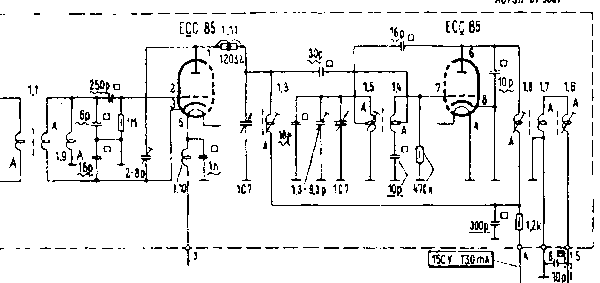
The first triode (buffer) can't be more than zero between 2 & 3 (g to k) as the 250pf is likely mica. polystyrene or ceramic and only connects to coils. The 1M Ohm is grid leak, it will be slightly negative on pin 2 (to chassis / 0V) if you measure with a 10M Ohm DVM when ECC85 is inserted. The second triode is a self oscilating mixer. A 30 pf capacitor (again NOT paper, but mica polystyrene or ceramic) isolates the transformer coil to pin 7, the grid. Pin 8 is the cathode. The 47k resistor provides the grid bias. If you use a probe with 2M resistor cut to 1mm long at one end to pin 7 to a 10M DVM (connecting direct will kill the oscilation) you'll see maybe -3V to -5V, I'm not sure, though with no ECC85 fitted the voltage on pin 7 to chassis (0V) or cathode pin 8 will be zero.
An example ECC85 circuit, not same circuit as in this set.
If 2 to 3 and 7 to 8 are both zero on empty socket then the ECC85 is faulty or there is something very unlikely faulty or wrong.
To thank the Author because you find the post helpful or well done.
siemens: E9 Hot Tube!
Mike,
Thanks for your detailed response and sorry about the confusion I made regarding the nature of some of the capacitors which I called them paper! They were actually neither ceramic nor aluminum; they sort of rubber or compacted material which I thought paper. I attached photo of them (inside the red squares); they are whit oval round shape which uF values range between 0.001uF to 1uF. I changed a couple of them simply because they were discolored with brown spot and there is crack at one end.
I will ordered a new ECC85 tube since the one I have is pretty old and may it is faulty. The 2 to 3 and 7 to 8 pins connection on empty socket are giving some reading. after I get the new ECC85, I can tell if the problem is the socket, the tube ECC85 or there is some faulty connection somewhere in the system.
Again, I would like to thank you so much for your help and instruction. I think if I can get the VHF-FM waveband working, I will be a very happy man!
Best wishes
Ali
Attachments:- Capacitors (142 KB)
To thank the Author because you find the post helpful or well done.
siemens: E9 Pin connections
I can't see how pins 2 to 3 and pins 7 to 8 can have a voltage on the empty socket. Pin 1 and 9 are either side of the gap. With an empty socket: pin 2, 3, 4, 7 and 8 should all be zero volts (top view anti-clockwise). Pin 1 and pin 6 will have the same HT voltage when there is no tube, I think more than 150V DC, perhaps close to 230V (it's 150V only when tube insterted and at connection "4" on the sub-chassis, likely about 115V DC in operation on the ECC85 anodes, pins 1 and 6 ) . Pin 5 is 6.3V approximately AC. The UKW button must be depressed to turn on the VHF unit 150V HT supply.
On LW, MW, or Gram there should be no HT on the VHF unit.
You can try cleaning the socket with a little WD40, but only if seems very dirty. Some switch cleaners attack some plastics, even making them crumble. I don't know what the socket is made from.
Note that the VHF alignment is very tricky and any disturbance of the wiring, capacitors or replacement of the socket on a VHF circuit means the alignment has to be done from scratch.
To thank the Author because you find the post helpful or well done.
siemens: E9 Pin connections
Thank you Mike,
I will try to do measurement for the pins socket again and validate the values. Will try also to clean the socket carefully, with WD40, because there is a lot of solid dirt/dusts accumulated on the wiring and connections leading to the socket pins of ECC85 over the last 50/60 years!!. I am not going to play with the VHF alignment and related wiring simply because my knowledge is still pretty basic and I do not want to screw up the radio wiring system! It may be a simple cleaning process is required resolve the problem. I will keep you in the loop regarding any progress.
Regards
Ali
To thank the Author because you find the post helpful or well done.
siemens: E9 Pin connections
So, we are making some progress (sort of)! The ECC85 tube and related socket seem to be working fine after cleaning all the rest around the pins and socket. Voltage measurements are OK and the tube is not heating up anymore. However, it seems another tube (EL84), which is the tallest tube, is also heating up and you cannot even touch it after a few minutes when the power is on. The VHF/FM still producing cracking noise trying to find or focus on stations. The radio feels like a patient trying to tell me I have a pain! However, I cannot locate the source of the pain!
To thank the Author because you find the post helpful or well done.
siemens: E9 Pin connections
The EL84 does get too hot to touch.
If you can safely, measure the cathode voltage (should be positive) to chassis and the grid, should be zero.
The grid and cathode should both be zero without the tube.
Clean all the sockets.
To thank the Author because you find the post helpful or well done.
siemens: E9 Pin connections
I will spend another careful and meticulous cleaning session tonight! I am using air cleaner coupled with some WD40 and also electronic spray cleaner.
To thank the Author because you find the post helpful or well done.
siemens: E9 Pin connections
Hi Mike,
So I did clean the tube and the socket (EL84) thoroughly and I measured the cathode voltage which was zero...The grid gave a reading of 5.6 Volts. The anode gave a value of 256 Volts. Without the tube; the grid gives close to zero measurement values while the cathode is zero! Not sure about my electricity knowledge and how the grid has some electrons moving around while the cathode is zero! May be my measurement is not accurate because I was trying to keep the probes steady during the measurement and making sure my hand would not touch the live wiring system….Not sure what will be the next step either…
I will be waiting to hear your response, as usual, for this old radio puzzle!
Thanks
Ali
To thank the Author because you find the post helpful or well done.
siemens: E9 Pin connections
I Forgot to mention that, after the cleaning session, the indicator light (magic eye) seems to be responding to the cracking noise of the VHF/FM waveband!
To thank the Author because you find the post helpful or well done.
siemens: E9 Pin connections
"and I measured the cathode voltage which was zero...The grid gave a reading of 5.6 Volts."
You sure not -5.6?
I can't see how that's possible with the grid socket reading zero with no EL84 inserted. Do take care of DVM polarity and reporting of readings.
Do check value of the resistor from EL84 cathode to chassis with thhe set off:

Note Cathode voltage should be between about +6V and +7V and grid voltage zero, measured to chassis. The 5.6V is a little low, but possibly OK, not sure. Check the 150 Ohms with power off. You may have to wait for reading to stablise due to the 50µF capacitor, A reading between 135 and 165 Ohms is fine.
I'm still suspicious of the wavechange switches, that they are dirty. With power off and set upside down and hatch open at the bottom, operate ALL the switches repeatedly while cleaning.
To thank the Author because you find the post helpful or well done.
siemens: E9 Pin connections
Or have you mixed up pin 2 & 3? Grid is pin two and is nearer the gap.
Anticlockwise on top
Clockwise from underside.
You can get +5.6V on pin 3, or if you measure BETWEEN 2 & 3, with -ve of meter on pin 3, then grid is -5.6.
To thank the Author because you find the post helpful or well done.
siemens: E9 Pin connections
Hi Michael,
My Siemens Standardsuper E-9 Radio saga is still continuing! I very grateful for all your help. I am trying to fix it just for the sake of self satisfaction not to save money since my other radios have nice FM receptions. It is taking a long time but I work it during evening hours when I come back from work.
Anyway, you are right regarding that the cathode reading; it was 5.6V and grid was zero. I confused my self with the measurements at pin 2 and 3! With respect to the 150 ohms resistor, I got a reading of 146. So, things seem OK at EL84. I also clean the knobs and the switches thoroughly. Still got the usual cracking and thundering noise.
However, I noticed someone fixed the tuning dialing cord string for the UKW/FM Knob (see photo). Although, the knob operates properly (pressing and releasing), I wonder if this new added cord string is the reason for faulty UKW and if the stations were moved out of range completely (outside 88 to 108 MHz FM radio band) during the attachment of this string!
Best wishes
Ali
To thank the Author because you find the post helpful or well done.
siemens: E9 Pin connections
Sorry. Forgot to attach the photo in my previous e-mail. Here it is..
Attachments:- Dialing Cord String FM (70 KB)
- Dialing Cord String FM (70 KB)
To thank the Author because you find the post helpful or well done.
siemens: E9 Dial Cord
I'd be surprised if that is the issue. The tuning range isn't decided by the dial cord. If the pointer moves across without jamming and the signal is changeing, then the cord is fine. Generally if the cord is done wrong one of the following happens:
- Pointer stops before reaching right end.
- Pointer stops before reaching left end.
- The pointer / scale action is reversed compared with tuning.
- The pointer and tuning is correct but the knob goes in the wrong direction. Easy to do. Earlier sets with a direct drive on outside of drum and no idler gear inherently have the "wrong" knob sense.
It would be a very unusual design of radio where you could tune outside the normal range.
Crackling as you tune often is intermittant shorts or dirt on the tuning capacitor. Make sure set is unplugged.
Use a piece of card (a suitable thickness, or folded) with alcohol or surgical spirit to gently rub between the vanes of the tuning cap when fully open.
I don't remember how accessible it is. I've used cheap nail boards the right thickness to sand off any dents or bashes at an edge that short.
If you do find it's very dirty you need to be careful. WD40, oil, switch cleaner etc will shift the tuning. Hence using something that can dry off , some alcohol (IPA/Propanol, meths, surgical spirit etc). IPA is usually purest and used industrially for degreasing. The meths & surgical spirit have water and additives.
To thank the Author because you find the post helpful or well done.
siemens: E9 Dial Cord
Hi Mike,
Thanks for the information. I did clean the tuning vanes cap and the surrounding areas. The dialing seems to work fine (cord and range). Still no progress was obtained. So, I decided to take to an expert in antique radios lives and work in greater Washington Metropolitan area. He checked the radio carefully and told me it has Silver Mica Disease (SMD)! Which means it needs a lot of work and high cost to fix it and there is a high probability that the radio could damaged completely in the process! So, he improved the long and medium bands by connecting a loose wire and installed a new antenna and told me to forget about the FM reception for the radio.
So, this will be the end of the story regarding my Siemens E-9 radio which I still like so much!
I just want to thank you so much for all your help, instructions and responses to my so many questions and quires. I really appreciate all your e-mail responses which you sent in a timely manner.
Thanks Again
Ali
To thank the Author because you find the post helpful or well done.