tektronix: 555; Dual Beam Oscilloscope Data Description
tektronix: 555; Dual Beam Oscilloscope Data Description
General Information
The Type 555 Oscilloscope is a wide-range, dual-beam, laboratory instrument providing accurate measurements in the dc to 30 mc range. Two complete horizontal and vertical deflection systems permit completely independent operation of the two beams. Either of two plug-in time base units can control the sweep of either or both of the beams.
Both vertical channels utilize Tektronix plug-in preamplifier units. This plug-in unit feature permits you to select the bandpass, risetime, type of input, and sensitivity required for your application. This selection is made by choosing the proper plug-in unit for the application.
Special circuits incorporated in the Type 555 permit you to select an accurate, continously variable, delay in presentation of one of the sweeps. The sweep may be delayed from .05 µseconds to 50 seconds after application of a triggering pulse. This feature allows you to expand a selected portion of the undelayed sweep thereby permitting precise time measurements. Both the delayed and the undelayed sweeps are presented on the oscilloscope screen.
Vertical-Deflection System
Characteristics for both vertical channels are identical. The actual figures depend on the plug-in units used with the instrument. The following characteristics are given assuming that Type K Plug-In units are used:
Band pass DC to 30 mc (3 db down at 30 mc ±1/2 db)
Risetime: 0.012 microseconds
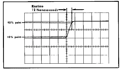
Fig. 1-1. Vertical risetime of the Type 555 Oscilloscope using a Type K Plug-In Unit.
Triggering Modes
Time Base A and Time Base B—AC, DC, and AC Automatic.
Triggering Signal Sources
Time Base A and Time Base B—External, Lower Beam, Upper Beam, and Line.
Triggering Signal Requirements
Internal from Upper or Lower Beam signal—A signal producing 2 mm of vertical deflection up to 2 mc. For frequencies above 2 mc increased signal amplitude is required.
External triggering—A signal of 0.2 to 10 volts.
Sweep will trigger on larger signals, but TRIGGERING LEVEL control operates over a ±10 volt range.
Sweep Rates
Type 21 and Type 22 - 0.1 microseconds to 5 seconds per centimeter in 24 accurately calibrated steps. Uncalibrated vernier controls permit sweep rates to be varied continuously between 0.1 microseconds and approximately 12 seconds per centimeter. Calibrated sweep rates are typically within 1%, and in all cases within 3%, of the indicated sweep rate.
Magnifiers
Displayed waveforms on either the upper or the lower beams can be expanded horizontally by a factor of 5, by means of separate sweep magnifiers. The magnifiers extend the fastest sweep rates to 0.02 microseconds per centimeter. Sweep rates are accurate to within 5% with the magnifiers on.
External Horizontal Inputs
External signals can be applied to sweep either of the two beams. Characteristics for both beams are identical.
Deflection factors—approximately 0.2 V/CM to approximately 20 V/CM. The deflection factors are uncalibrated and continuously variable.
Passband—DC to approximately 240 KC (3 db down point) with the EXT HORIZ GAIN control in the maximum gain position.
Input impedances—approximately 47 pf paralleled by 1 megohm with the HORIZ DISPLAY control in the X1 position.
Delayed Sweep
Sweep delay continuously variable from 0.5 microsecond to 50 seconds. Actual delay steps (between 1.00 and 10.00) are within 3% of the indicated delay from 0.5 µsec/cm to 50 sec/cm. Incremental delay accuracy is within 0.2%.
Time jitter-1 part in 20,000.
Cathode-Ray Tube
Type T555P
Phosphors—Type P2 phosphor normally supplied; P1, P7, and P11 phosphors optional. Other phosphors available on special order.
Unblanking—dc coupled.
Accelerating potential-10,000 volts.
Usable viewing area—total of 6 centimeters with 4 centimeters for each beam. At least 2 centimeters of overlap between the two beams.
Graticule
Illumination—variable edge lighting.
Markings—marked in 6 vertical and 10 horizontal 1-centimeter divisions with 2-millimeter markings on the centerlines.
Amplitude Calibrator
Waveform —square-waves at approximately 1,000 cycles.
Output voltage-0.2 millivolts peak-to-peak to 100 volts peak-to-peak in 18 steps.
Accuracy —peak-to-peak amplitude of square-waves within 3% of the indicated voltage.
Power Supplies
Electronically regulated for stable operation with widely varying line voltages and loads. Line voltage requirements-105 to 125 volts, or 210 to 250 volts.
Power requirements —maximum of 1050 watts.
Line frequency-50 to 60 cps.
Output Waveforms Available
Delayed trigger pulse —approximately 5 volts in amplitude, occurring at the end of the delay period.
+Gate A-20 volts peak-to-peak with the same duration as the A sweep.
Sawtooth A—A sweep sawtooth waveform, 150 volts peak. +Gate B-20 volts peak-to-peak with the same duration as the B sweep.
Sawtooth B—B sweep sawtooth waveform, 150 volts peak.
Ventilation
Forced filtered air. Thermal relay interrupts instrument power in the event of overheating.
Construction
Aluminum-alloy chassis and three-piece cabinets. Photo-etched anodized panel, blue wrinkle-finished cabinet. Dimensions: Indicator Unit: 24" long, 13" wide, 20" high. Power Supply Unit: 17 1/2" long, 13" wide, 10". high.
Weight —Indicator Unit: 68 pounds. Power Supply Unit: 45 pounds.
Accessories
Time-base plug in extension (013-013).
Attenuator Probes (10X Attenuation), 010-020. 1—Inter-unit cable (012-032).
Binding-post adaptors (013-004).
Test lead (012-031).
Green Filter (378-514).
conductor power cord (161-010).
Instruction Manuals.
3 to 2-wire adapter, 103-013.
To thank the Author because you find the post helpful or well done.