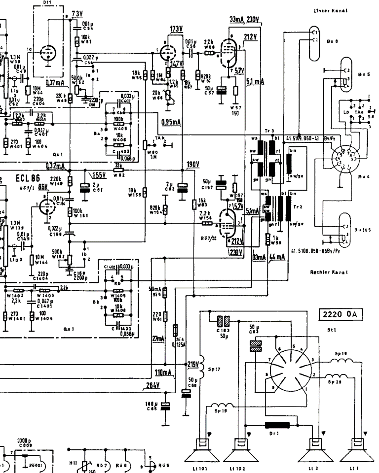
telefunken: 2194; Concertino - Audio circuit questions
? telefunken: 2194; Concertino - Audio circuit questions
This model has a stereo audio circuit. From studying the schematic, it seems to have an extra triode in the left channel. After the volume control, the audio signal for each channel goes through through a triode. In the case of the left channel, that triode is part of the EABC80 and in the case of the right channel the triode is part of the ECL86. The output of the right channel triode goes directly to the pentode section of the ECL86. The left channel, however, goes through the triode section of the ECL86 before it is applied to the pentode section.

I have two questions concerning this model.
- Why the extra stage in the left channel?
- How to adjust W66, the 20k trim potentiometer in the cathode circuit of the second triode of the left channel?
Best Regards, Jim
Improved because the circuit diagram was too large.
To thank the Author because you find the post helpful or well done.
Phase inverter

The extra tube is a phase inverting stage because the deep frequencies below 300 Hertz run on the push-pull stage with a special coupling transformer. The higher audio frequencies will use the smaller transformers as two single amplifiers, but the polarity is vice versa depending on the changed phase.
This application had been described in depth in the electronic magazine FUNKSCHAU in 1957/1958. Some years ago I took some copies of this article but today I didn't find it within my other paperwork. My guess is - I shreddered the copies with other material....
Perhaps another RMOrg member owns this magazine and is able to transmit the original - or a translated version - to you.
The trim potentiometer is an adjustment for the phase inverter; the 18 kOhm resistor leading to the plate must be also with the same value - depending on tolerances - as the summary of the cathode resistor(s) 1.2 kOhm and the adjusted value of the trim pot. Only when both Ohm values are equal the phase inverter will work well resp. as designed.
G.S.
To thank the Author because you find the post helpful or well done.
Unity gain
Thanks for that. I would like to see the article you refer to. German would be fine as I can have it translated.
So I assume then that with the cathode resistance matching the anode resistance the gain of this stage would be -1? I'll check this on my 2194.
Certainly an interesting design.
To thank the Author because you find the post helpful or well done.
No gain

You are absolutely right: no gain, only inverting for the push-pull function.
G.S.
To thank the Author because you find the post helpful or well done.