The Overlooked Art of Dial Calibration...
The Overlooked Art of Dial Calibration...
The Overlooked Art of Dial Calibration and How Stations Found Their Place on the Scale
Introduction: Why Calibration Matters
Every vintage radio restorer eventually learns that a radio dial is not always an honest storyteller. Tune to 700 kHz and you might land at 723. Spin toward 1000 kHz and the voice comes in at 1025. To the casual listener this is an oddity. To restorers, it is a challenge that cuts to the heart of authenticity. Dial calibration is about more than numbers; it is about honoring the promise radio makers once made to their buyers: that a glance at the dial would reveal the world. In this long-form article, we explore the history, the mechanics, the electronics, the bench tricks, and several case studies that together make dial calibration one of the most fascinating but underappreciated aspects of radio restoration.
1. The Evolution of Dial Calibration
Radio’s first listeners had no dials at all. Crystal sets of the 1910s required a steady hand moving a whisker across a galena crystal, listening for faint signals. Calibration was entirely personal: a penciled note in a notebook, 'Move slider to coil turn 17 for Pittsburgh.' As broadcasting took off in the 1920s, the demand for visual scales was immediate. At first, dials were crude - cardboard discs with approximate numbers. Manufacturers like Atwater Kent, RCA, and Crosley knew buyers wanted precision, but the technology of the day made exact scales elusive.
By the late 1920s, vernier tuning and drum dials appeared. Vernier dials, with reduction gears, allowed fine control, stretching a small turn of the knob into large, precise motion of the capacitor. Drum dials offered long, linear scales, often lit from behind, making tuning both accurate and dramatic.
In Europe, the philosophy was different. Rather than numbers, many sets used city names on glass scales. A listener in Berlin could find 'Paris' or 'London' glowing softly. These dials made radios cultural windows, though they required recalibration as stations shifted frequency or propagation changed. American makers, by contrast, emphasized numeric accuracy, reflecting consumer preference for measurable precision.
By the 1930s, calibration was a selling point. Zenith’s 'Robot Dial' and Philco’s 'Shadow Meter' claimed better accuracy. Multi-band shortwave sets expanded the challenge, as calibration across bands from 500 kHz to 18 MHz strained both mechanics and electronics. World War II accelerated the demand for accurate dials, with military sets requiring alignment not just for convenience but for survival. Postwar consumer radios benefited from improved capacitors and more stable oscillators, but even then, dials drifted. Calibration remained a technician’s craft - and still does today.
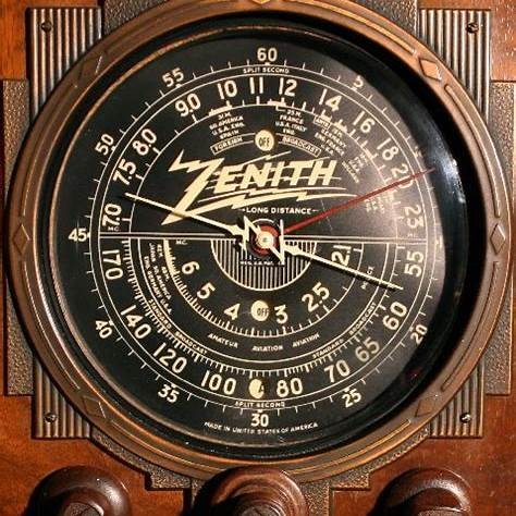
A 1920s Zenith dial showing prominent numerical markings.
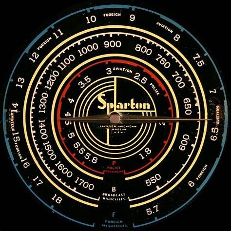
A 1930s Sparton dial - more elaborate, closer to European aesthetic.
![]()
A 1930s Philco with clearly numbered scale (US style).

An Atwater Kent 1920s numeric dial - old American numeric style.
2. Mechanical Systems: Cords, Pulleys, and Pointers
Behind the smooth sweep of a pointer lies a deceptively complex mechanism. A knob turns a shaft. The shaft drives a cord. The cord winds through pulleys, around drums, and finally pulls the pointer. This translation introduces opportunities for error. Common systems included:
- Straight-pull cords: simple but prone to slippage.
- Crossover cords: used to reverse pointer direction, but increased complexity.
- Ladder pulley systems: found in consoles, smooth but sensitive to tension.
- Drum dials: cylinders with long printed scales, requiring exact cord wrapping.
Mechanical failure is inevitable. Cords fray. Springs weaken. Pulleys wear unevenly. Even a millimeter of slack produces significant pointer error. Humidity warps paper or celluloid scales. Some scales shrink, compressing markings so that stations no longer align. Paint fades, leaving ghostly remnants. Each of these issues challenges restorers.
Solutions abound. Restorers often replace cords with braided nylon, Dacron, or silk fishing line. Beeswax applied to cords improves grip. 3D-printed pulleys substitute for cracked originals. Springs can sometimes be repositioned to regain tension. Warped scales can be flattened between glass sheets with gentle humidity. In some cases, digital reproductions provide replacements, preserving originals as artifacts. Every solution must balance originality with usability, a judgment call restorers make daily.

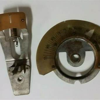
Dial Cord Stringing – front-view layout showing pulley positions and string wrap angles.

Close-up showing the tuning gang, spring, and how the cord winds.

Diagram with multiple pulleys and spring layout, useful for more complex sets.

Example from a Zenith model showing real pulley geometry in a scale publication.
3. Electrical Drift and Alignment
Even perfect mechanics cannot compensate for drifting electrons. Oscillator coils change inductance with temperature and age. Paper capacitors absorb moisture, mica capacitors crack, electrolytics dry out. These changes shift tuning, causing the dial to wander.
Classic alignment procedures, detailed in Rider manuals, followed a four-step pattern:
1. Align intermediate frequency (IF) stages, usually 455 kHz.
2. Adjust oscillator trimmer at high-end frequencies.
3. Adjust oscillator padder at low-end frequencies.
4. Align RF and antenna trimmers to maximize signal strength.
This process restored tracking, ensuring that the oscillator and RF stages moved in harmony. Shops in the 1930s performed these procedures daily, using signal generators, oscilloscopes, and sharp ears. Today’s restorers use digital counters, SDRs, and modern signal generators, but the method remains the same.
Safety cannot be overstated. Isolation transformers prevent shocks. Variacs allow gentle power-up. Dim bulb testers reveal shorts. Patience, documentation, and methodical adjustment are the restorer’s allies. Missteps can ruin coils or damage rare parts. Done well, alignment restores not just performance but authenticity - the joy of seeing a pointer land exactly where it should.

Alignment being performed with modern signal generator
4. Bench Tips and Tricks
Decades of restoration experience have produced a library of tricks that save time and preserve originality. Among the most valued:
- Tighten spring anchors before replacing cords entirely.
- Use wax pencils to mark temporary calibration points on the dial.
- Guide new cords through paths using dental floss as a pull.
- Flatten warped scales between glass panes, misted lightly with distilled water.
- Print replacement dials on transparency film when originals are beyond repair.
- Plot calibration charts before and after adjustment, graphing actual vs. dial frequencies.
- Use non-metallic alignment tools to avoid detuning circuits.
- Pair vintage sets with SDRs to visualize drift in real time.
- Keep calibration logbooks for each set restored, building an archive of data.
- Substitute nylon fishing leaders for missing tension springs.
- Use beeswax sparingly on cords to reduce slippage.
- Create cardboard templates of cord paths before removal to aid reassembly.
- Calibrate against reliable time signal stations (WWV, DCF77) when available.
Each of these tips may seem small, but together they form the restorer’s toolkit for efficient, authentic calibration.

Example of “before vs after” calibration chart (hand-logged style)

Example of Dial Calibration Log” graph template filled in by hand
5. Case Studies
Theory finds its test on the bench. Several restorations illustrate calibration in practice:
**1938 Zenith Console**: Arrived with a 20 kHz error across the AM band. Restringing and pulley shimming reduced error. Oscillator trimming brought accuracy within 5 kHz. A before/after calibration chart documented the transformation.
**Philco Cathedral**: Post-recap, pointer misalignment plagued tuning. Comparison with an original scale revealed the issue. Adjusting the pointer mount and oscillator alignment restored usability.
**Grundig Shortwave Receiver (1950s)**: Multi-band alignment required patience. Each band was calibrated separately. Tracking errors corrected with individual trimmers. The final result made shortwave listening practical again.
**Wartime Military Receiver**: Accuracy here was mission-critical. Calibration involved both mechanical and electrical steps, verified against time signal stations. For soldiers, miscalibration could mean missing orders or signals. Restoring one today is a reminder of how vital calibration once was.
These examples show that calibration is never routine. Each set has its own character, its own quirks, and its own demands on the restorer.
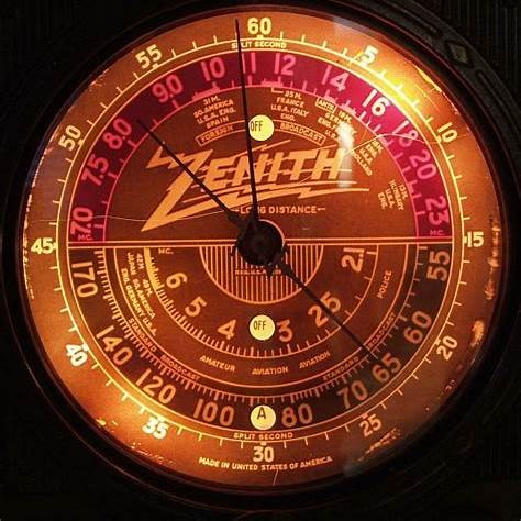
Zenith dial before and after alignment

Lit, in-set scale (Philco 37-60)
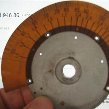
Raw scale part photo (likely 60-series)
Scale + lighted indicator assembly

Grundig shortwave band spread scale

Military set being aligned
6. Conclusion: Preserving an Overlooked Art
Dial calibration rarely earns the glamour of cabinet refinishing or the drama of reviving a silent chassis. Yet it is calibration that makes a set truly authentic. A radio that not only plays but points accurately connects us directly to the expectations of its original owner. It restores trust in the instrument and satisfaction in its use.
As restorers, our job is not just to make radios work, but to make them work as they once did. That means honoring the overlooked art of calibration. By sharing tips, documenting results, and inviting others to contribute their methods, we ensure this knowledge endures. When a pointer glides to 1000 and a station comes alive exactly at 1000, we hear more than a broadcast. We hear history, aligned once again with truth.
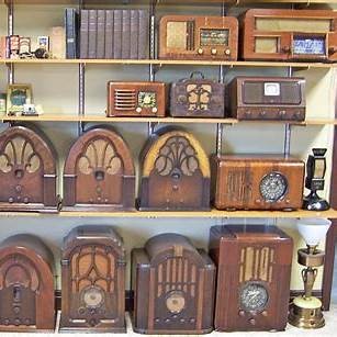

Collection of restored radios glowing with dials aligned
To thank the Author because you find the post helpful or well done.