The Philips Red valves series, part I
The Philips Red valves series, part I

Use of this article (entire thread, any parts) is not permitted for commercial purposes!

Following the range of side-contact valves of the C-, E- and A- series (CK1, CF1, EK1, EF1, AF3, AK2, AL1, etc..) established in 1934/1935, Philips brought out a new range, the so-called "Red E- series" in 1936.
These were fitted with the side-contact base, as before. Instead of silver or gold, the outside metallising now had a red coloured coating, which they were named after.
The signal valves were considerably smaller and they had significantly shorter leadout wires because of the very short structure of the pinch. Compared to the previous valves, they had improved characteristics. The heater consumption was only half that of the A- and C- of valves and only 2/3 of the American signal valves.

The comparison of the EF5 with the AF2 of 1934, the AF3 of 1935, the EF41 of 1947 and the EF89 of 1954 clarifies the progress.
They were the inexpensive glass answer to RCA's original metal octal valves of 1935 and probably served as a model for the American GT series of two years later.
The heater voltage was now standardised at 6.3 V. There was now no need for different valves for A.C. mains sets (previously the 4-volt A- series such as AK2, AF7, etc.) and car radios (previously the old 6.3-volt E-series, like EK1, EF1, etc.) The heater current of all the signal valves was now 0.2 A, so these valves could also be used in AC/DC sets with series heater strings.
Thus, the new "Red" EF5 replaces the AF3 (alternating current), the CF3 (AC/DC) and the EF2 (car radio). AC/DC sets now only needed the output and rectifier valves from the old C- series.
The original series of 1936 consisted of the types EK2, EF5, EF6, EB4, EBC3, EL2, EL3, EL5, EM1, EZ2, EZ3 and EZ4.
1937 The types EBF1, EBL1, EH2 and C/EM2 appeared.
1938 The EAB1, EBF2, ECH2, EF8, EF9, EFM1, EK3, EL6, ELL1, 1882 and 1883 appeared.
1939 The ECH3 and EM4 were added.
1940 The ECH4 and ECF1 more or less completed the main development.
The red series came out mainly as E- series with 6.3 V heaters and side-contact (pot - or elephant's -foot or CT8) base. Some additional types of the C- series with 0.2 A heater current came out.
Starting from 1938, the first octal-based Red valves appeared in Great Britain only.
1940 the red series of valves with octal bases appeared as the U- series with 0.1 A heater current as well as the D- series with 1.4-volt filaments for battery operation.
1948 and 1949, from Valvo in Germany, the previous red range of valves now appeared in gold as a temporary solution, until the industry was able to manufacture the more modern Rimlock valves.
These were the types EBF2, EBL1, ECH4, EF6, EF9, EL8, EM4 for alternating current and the types UBL3, UCH5, UF5, UF6, UL2 and UY4 for AC/DC.

France apparently served as test market for these new valves, because this series was presented there in May 1936; in other countries it only appeared in 1937.
The French edition of "PHILIPS Bulletin Technique" (above) from May 1936 and more than one year later the English edition of "PHILIPS Setmakers Bulletin" (below) from August 1937 also prove this clearly.

They quickly became very successful in practically all countries of (Continental) Europe, except Germany, so they were known as the "Transcontinental" series.![]()
Red valves in Germany?
In contrast to earlier valve development, this time Telefunken did not play any part in the red valves. Quite the opposite, with the virtual valve monopoly Telefunken in Germany preventing from introducing these progressive new valves.
It is obvious that Telefunken already planned at this time to adopt the technology of the 1935 USA-produced metal octal valves.
In order not to appear as a mere copy, the future Telefunken steel valves had, of course, to look completely different from their American models, hence it took until 1938 for their release.
Only with these Telefunken did have a comparable range to compete with the red Philips valves of two years earlier. So in Germany, for a long time one had to be content with the A and C series, whose small-signal valves in particular were technically undeveloped, and antiquated compared to the "Red Series".
An exceptional case occurred in 1938 following the "Anschluß" (annexation of Austria by Nazi Germany.) There was no Telefunken valve monopoly there, and Red series valves were previously far more common.
Since Austrian companies could now supply their sets to the entire German realm (the Groß-Deutsche Reich), the sale of the "Red Series" valves in Germany was permitted, but only as part of the Austrian sets and spare parts for them.
This opportunity for Philips lasted only briefly, since the Austrian companies were immediately forced to change their designs over to Telefunken steel valves.
A further exception was radios with company names of German setmakers which contained Red valves. These were however "Besatzungsradios" (occupation radios), which foreign companies in countries occupied by the Wehrmacht (Hitler's army) had to manufacture, which were then sold as alleged German export sets into third countries. -Except for the company name, nothing was German about these sets.
To thank the Author because you find the post helpful or well done.
The Red series, first released May 1936

EB4:
Double diode, replaces AB1, AB2, CB1, CB2, EB1 and EB2.
For demodulation (detector) and producing automatic volume/gain control voltage.
First European double diode with screening / shielding between sections and separate cathodes, modelled on the American 6H6, with consequent greater design freedom compared to the predecessors with common cathodes. If there had been frequency modulation at that time, the diodes of the EB4 could have been used in the ratio detector.

EBC3:
Double diode triode, replaces ABC1, CBC1 and EBC1. For use as detector, AGC and AF pre-amplification. gm 2.0 mA/V µ30 Ri 15k. Due to its low internal resistance, it could be used as an oscillator triode or, if necessary, as an AF transformer driver.

EF5:
Variable-µ pentode, replaces AF3, CF2, CF3, EF2 and EF3. For HF- and IF- amplification with fixed screen grid voltage.
gm 1.7, with very similar characteristics to the American types 6D6/6U7.

EF6:
Straight pentode, replaces AF7, CF1, CF7, EF1 and EF7. As detector, HF or AF- amplifier, gm 1.8, amplification factor 175. Usable, triode-connected, as AF- transformer driver. The later Telefunken EF12 has very similar data to the EF6.

EK2:
Octode for frequency conversion, replaces AK2, CK1 and EK1. As a frequency changer, conversion gain is 0.55; with improvements over the predecessors, particularly regarding frequency stability. However, the application of AVC on the SW band is not recommended.

EL2:
Output pentode for car radios, replaces EL1 and CL1. Pa 8 W, Ia 32 mA, gm 2.8 mA/V; Ih 0.2 A. The characteristics are identical to that of the predecessor EL1, except the heater current being reduced from 0.4 to 0.2 A, to allow series-connection with other valve(s) of the same series, this being important for 12-volt car radio use. The anode dissipation was increased at the same time from 5 to 8 W, which was accomplished by changing the grid bias from -23 V to -18.5 V, so this valve then ran at 32 mA instead of 20 mA.
The EL2 is the fore-runner of the later car radio and low power output valves EL32, EL42, EL95, ELL80 and ECLL800 in which, starting from the EL42 the anode current was reduced to 26 mA and starting from the EL95 to 24 mA.
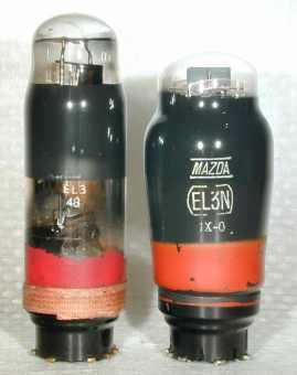
EL3 / EL3N:
Output pentode, supersedes AL1, AL2, AL3 and AL4. Pa 9 W, Ia 36 mA, gm 9 mA/V; Vg1 -6 V.
These continued with the technology of high-slope output valves, which began with the AL3. Requiring a signal of only 4.2V at the grid, in a simpler ("short") superhet, the first AF stage could be omitted, and distortion-reducing negative feedback could be used in better sets. In a regenerative set, an EF6 is sufficient as a leaky grid detector to drive an EL3 to full output. The large cathodes provide also for a long life span of these output valves. The old EL3 has an unmistakable appearance, as the envelope is cylindrical from the base then has a short inwards tapered shoulder to the tubular top section, while the EL3N (N = new) had a normal dome-shaped glass envelope.
With a heater current of 1.2 A, the original EL3 had a similar heater power to the AL3. Only a few months later, the EL3N with a heater current reduced to 0,9 A appeared. The old EL3 still had a cylindrical cathode, as did the AL3. Shortly afterwards, it was found that the grid winding could be made very much better and in equidistant alignment to an oval (actually elliptical) cathode than to a round one.
With this, we see that the efficiency increased and thus the heater consumption was reduced, also the distortion is reduced with smaller signals. The EL3N and the AL4 were the first to use this oval cathode. Since that time in nearly all later output valves, oval- or flat-profile cathodes were used. The EL3 was the practical prototype the following types EBL1, EL11, EBL21, EL33 (= 6M6), EL41, EL84 and ECL86.

EL5:
High-power output pentode, the European counterpart to the American 6L6.
Introduced January 1937. (for the picture unfortunately only a Valvo AL5 was available, which looks like the EL5, except for a golden instead of a red skirt.)
Around the same time as, or even slightly before, the release of the famous RCA- Beam power tetrode 6L6, the European counterparts EL5 and AL5, which are electrically equivalent except for the heater voltage, appeared. The EL5 with the modern 6.3-V heater was always supplied by Philips as a genuine pentode with (wound wire) suppressor grid (g3), 1.3 A heater and oval cathode, while the Telefunken AL5 with conventional 4-V heater was often (or always) made as a Beam power tetrode (BPT) like the 6L6. The 6L6 is always a Beam power tetrode with beam forming plates instead of suppressor grid and 0.9-A heater, flat-profile cathode, but in characteristics and output there is a remarkable similarity to the EL5 and AL5.
While RCA primarily promoted the "Beam power" and beam focusing principle with the 6L6 for low harmonic distortion output signals, Philips argued they could achieve the same goal and still other advantages over the Beam power tetrodes with the special construction of the EL5. Which principle is really the better for AF- output valves, is rather a matter of opinion; both kinds of valves are still in use today (EL34, EL84 as pentodes, 6L6GC, 6550 as BPT). For the BPT at least the manufacturing costs count in its favour, since instead of a wound wire suppressor grid only one sheet metal frame is necessary. With TV line-output valves, the Beam power tetrode clearly found a place with the PL36, PL519 etc.
In Class A use, the EL5 achieved an output power of 8.8 W, in push-pull circuit 19.5 W. The types 4689, 4654 and EL50 were brought out later with the EL5 construction, which all had the characteristics of the EL5, but were further developed for higher voltages and higher power output:
The 4689 also called the EL5/375 (meaning 375 V operating voltage)
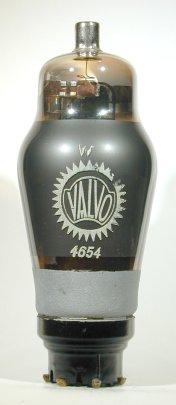
The 4654, also known as EL5/600, which was replaced by the backwards-compatible EL50.

EM1:
First European magic eye, also called "tuning cross" replaces neon TI lamp and shadow-pointer movement.
After 1935 in the USA, the 6E5, the world's first cathode ray tuning indicator "eyes" appear. In 1936 Philips brought out the EM1 and the AM1, (4-volt version of the EM1), the first European valves of this kind. AM1 and EM1 appeared first in the Philips special valve series as 4677 and 4678, as "M" was not yet assigned to tuning indicator eyes.
As with the 6E5, behind a light shield, the EM1 had an internal amplifier triode whose anode was connected to the deflection rods. In contrast to the 6E5, which only had one deflection rod and hence only a single shadow display, the EM1 displayed four sectors, so this valve was also called tuning cross. The luminous display was very pretty; it looked like a Maltese cross or four-leaf clover, with variable-width leaves. The display was not very bright, so the fluorescent screen end of the envelope was inset and the sides of the envelope were painted red, to be safe from light falling on the side (scale illumination) which made the display more distinct. Later versions abandoned the inset of the end. The amplifier triode of the EM1, like the 6E5, did not have a variable-µ characteristic, and thus the same disadvantages. Also, originally there was no grid around the ray cathode, which caused an excessive beam current and wore out the fluorescent material too quickly. Once this fault was realised, this grid was included in later versions.

EZ2:
Car radio full-wave rectifier valve, supersedes EZ1.
2 x 350 V, 60 mA, 0.4 A heater, Vh-k max. 500 V. The maximum AC input voltage of the EZ2 was increased to 350 V, against 250 V of the previous EZ1, which were not particularly reliable and were often inclined to arc over.
EZ3 and EZ4
For normal alternating current sets, the EZ3 and the EZ4 were the first indirectly heated full-wave rectifier valves to be offered in continental Europe in place of the earlier directly heated types such as AZ1 and AZ4. The directly heated rectifier valves present a problem, in that they supply current much earlier than the slow-acting indirectly heated valves start to draw current. The consequence of this is that in this meantime the HT rises very high and can destroy the electrolytic capacitors. The solution to this problem consists of making the rectifier valve also indirectly heated.
A further advantage of indirectly heated rectifier valves is their distinctly lower internal resistance than with directly heated valves, achieved by the better cathode efficiency and the equally important small cathode/anode spacing. Through this, there are fewer voltage fluctuations due to changes in load current caused by AGC action or due to varying output of push-pull power amplifiers. If, a directly heated AZ1 were replaced by an indirectly heated EZ3 in existing equipment, the HT would increase by over 20 V, which would over-run the receiver valves. Therefore the mains transformer must supply a correspondingly lower voltage when using an indirectly heated full-wave rectifier valve. An additional advantage of indirectly heated rectifier valves is that their heater can be connected in parallel with the other valves and therefore does not need its own separate heater winding. A condition is however that the heater to cathode insulation is adequate, which is the case with the EZ2 and EZ3, but not, however, with the EZ4, which still needed its own heater winding.

EZ3:
Full-wave rectifier valve, indirectly heated, replaces AZ1.
2 x 500V, 100 mA, Vh-k max. 550V.
Despite the advantages of the indirectly heated rectifier valves many equipment manufacturers still used the directly heated AZ1 with the red series instead of the EZ3, as did Philips with their own sets. Only many years later, with the types 6X4 (= EZ90), 6BX4, EZ80 and EZ81, it became general practice to simply connect 6.3-V rectifier valves in parallel with the other valves without an additional heater winding .

EZ4:
Full-wave rectifier, indirectly heated, supersedes the AZ4 and 1561 (RGN2004), for larger receivers and power amplifiers. 2 x 400V, 175 mA, 0.9 Ah. As Vh-k max. = 0V, its own heater winding is needed, which must be connected to the cathode. This is the first indirectly heated rectifier valve of this performance class in continental Europe. With 2 x 400 V a.c. input, it slightly betters its nearest similar types 83-V and 5V4G (2 x 375 V 175 mA). The heater power is substantially smaller (5,67: 10 W) and their anode cooling fins substantially smaller than the 5V4G's. With the amazingly small dimensions of 85 x 37 mm (h x ø) (like ECH3 or EL8) it has easily the best ratio of power output to heater power and size of its time.
Possibly this relationship was too close and led to unreliability, because later rectifier valves were again more conservatively rated, e.g. the EZ81 allows, with 1 Ah, only 2 x 350 V 150 mA.
To thank the Author because you find the post helpful or well done.
1937 additions

EBF1:
Double diode + variable-µ pentode, for HF- IF- and AF- amplification with fixed screen grid voltage, gm 1,1; 0.3 Ah.
The EBF1 is actually a variable-µ pentode double diode 6B7 or 6B8, re-packaged with a side-contact base, same top cap as the 6B7 and red metallising.
The alien origin is recognisable by the heater current of 0.3 A, mismatching the red series, but exactly suited to the American valves, as well as by the glass envelope, which is clearly larger than the other red valves to date such as EBC3, EF5 or EK2, but corresponds exactly to the American ST-12.
Probably, a double-diode pentode was wanted quickly in the red series, to avoid customers changing to American valves, where they had already made such a type for years. Since the Philips company also produced 6B7s and 6B8s, they simply took the unbased blanks of it, provided them with side-contact bases and red metallisation and, voila!, the EBF1.
The 6B7/6B8 origins required masking by intentionally altering the data slightly, e.g. 1.1 mA/V instead of 1.3 of the 6B8. This perhaps served to let it appear as their own development in order to circumvent licence royalties to the 6B7's designer (RCA).
If this had been their own design, surely they would not have chosen this heater current nor selected this shape of envelope, as was also later the case with the EBF2.
The EBF1 was obviously never brought out under the name Philips.
Dario and Mullard became known as the makers, and although Valvo was not allowed to sell this valve in Germany, it was also sold under their label exclusively for export. (Nobody knows if Valvo actually has made those 6B7s )
The EBF1 is the first double diode variable-µ pentode with side-contact base. The EBF1 was probably not very widespread in Continental Europe, but as reported in the "FunkGeschichte*" No. 85, page 217, Ernst Erb discovered EBF1's even in Australian receivers.
*magazine of German radio collectors.

EBL1:
Output pentode + double diode, the pentode section corresponds to that of the EL3, with additional diodes for HF/RF detector and rectifier for AGC,
released January 1937.
Pa 9 W, Ia 36 mA, gm 9 mA/V; Vg1 -6 V.
The EBL1 was meant for the construction of simple ("short") superhets without 1st AF amplifier stages, wherein the diode output signal drove the output pentode directly, e.g. with the valve complement EK2, EF5, EBL1 and EZ3. Since, however, the sensitivity of such receivers was not always satisfactory, 4-valve sets with 1st AF stages, using the pentode section of the 6F7 American combination valve as IF- amplifier and the triode section as AF amplifier were immediately brought out.
With a valve line-up, e.g. EK2, 6F7, EBL1 and EZ3 , the first circuits with standard valves were designed, in which a complete superhet consisting of frequency changer, IF, diodes, AF- pre and output stage and rectifier valve needed only a total of four valves, (if one ignores the very special multiple-valves of the German set- and valvemaker Loewe).
Later, in place of the 6F7, the ECF1 and the ECH4 were adopted for this purpose in the Red series.

EH2:
Variable-µ heptode, supersedes AH1, CH1 and EH1;
released January 1937.
gm 1,4; gc 0.4 .
The EH2 is intended for two different applications, like the the 6L7:
1.: As mixer valve with separate oscillator injection. This application is new compared to their predecessors AH1, EH1 and E449/RENS1234, which are not recommended for this.
2.: As variable-gain HF- or AF- amplifier requiring only a small control voltage.
Re: 1.: Since the octode EK2's performance as a mixer valve is not satisfactory in all cases, (particularly on short waves), the heptode EH2 was planned for higher performance mixer stages. The input signal is applied to the first grid. The oscillator signal, supplied by an additional valve, e.g. a EBC3 or a triode-connected EF6, is applied to the third grid. A mixer of this design is even gain-controllable (e.g. AVC/AGC) on short waves without frequency variation, the internal noise at high frequencies is small, the input impedance is high, the conversion gain, with gc of 0.4mA/V, is rather moderate.
Re:2 .: As with the the earlier AH1, EH1 or E449, the EH2 can be used as an RF- or LF- amplifier, in which a small control voltage gives a large range of control. The input signal is applied to the first grid, and the control voltage to either the third grid alone, or to the first and the third grids equally. Generally, the EH2 can be used also as adjustable AF- amplifier, e.g. as dynamic range compressor/expander or automatic level control.

C/EM2:
Magic eye, for tuning indication and AF preamplification.
Released July 37
The C/EM2 can be counted only conditionally among the Red series. It was offered by Philips only in countries in which Telefunken was also strongly represented. Actually it is the 0.2A / 6.3V version of the AM2, a Telefunken development. It was used almost exclusively in AC/DC sets with C-series of valves, whose AC counterparts used the AM2. In principle it would have been sufficient to call this valve EM2 as many other small-signal valves of the Red series had both 6.3V heater voltage (letter E) as well as 0.2A heater current (i.e. calling them EM4, ECH3, EF9, etc. instead of calling them C/EM4, C/ECH3, C/EF9 etc; C/E expresses 6.3V heater voltage as well as 0.2A heater current). Since, however, the sale of the Red valves in Germany was prevented by the Telefunken monopoly and these therefore remained unknown there, the additional C was to show the C/EM2's affiliation to the C-series.
Apart from tuning indication, the C/EM2 and the AM2 can be used additionally for AF preamplification. For this the internal triode system is used only as an AF amplifier, while the deflection voltage is applied to the grid of the display system. This must however stay within the range of -6... +3V and can only be obtained by tricky circuitry, e.g. from the screen-grid voltage of the IF stage.
Of all well-known magic eyes, the C/EM2 and the AM2 have the least attractive display. With maximum input, the light sectors cannot be closed and there always remains an ugly gap between them. With weak signals the edges of the light sectors become ever more blurred, until only two "dirty" green marks remain, unless the operating range is suitably limited.
Continued at part II
To thank the Author because you find the post helpful or well done.