TM curve family
TM curve family

Fellow tube collectors,
Recently, I acquired two spectacular replicas of the TM tube originally designed in 1914.
RMorg officer Dr Ruediger Walz helped design and fabricated these replicas and he shows his laboratory and history of his replicas at www.ruediger-walz.de. The original design of the replicas was a joint effort with his late friend Franz Pemmerl.
I read about Dr Walz's replicas from an article in Tube Collector Vol 11 No.6 December 2009 published in USA by TCA - Tube Collectors Association.
The tubes were shipped by Dr Walz with serial numbers and a printed grid voltage to anode current single curve plot, as was customary for early European triode data sheets.
Tungsten Filament Temperature
The filament in these triodes is made of pure Tungsten and, as such, must run at a much higher temperature than even Thoriated Tungsten of 1920's tubes or the later rare earth coated cathodes.
One measure of the temperature is the pure white light that shines from the filaments when running at rated voltage around 3.4V and 550mA. A more accurate measure of filament temperature can be inferred from the increase in filament resistance between room temperature (300K) and at running temperature.
The average cold resistance between the two tube samples was 550mOhms at 300K, and the average hot running resistance was 10.7_Ohms. From this resistance increase we estimate a filament temperature of 3230K as a simple proportion. This number could be off a few percent from the slight curvature of the temperature coefficient of Tungsten.
Wikipedia defines the color temperature range for an incandescent light bulb between 2700K and 3300K. This is consistent with the observed White light from the filament.
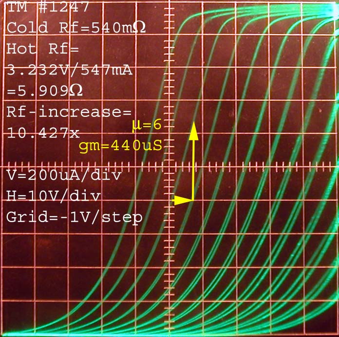
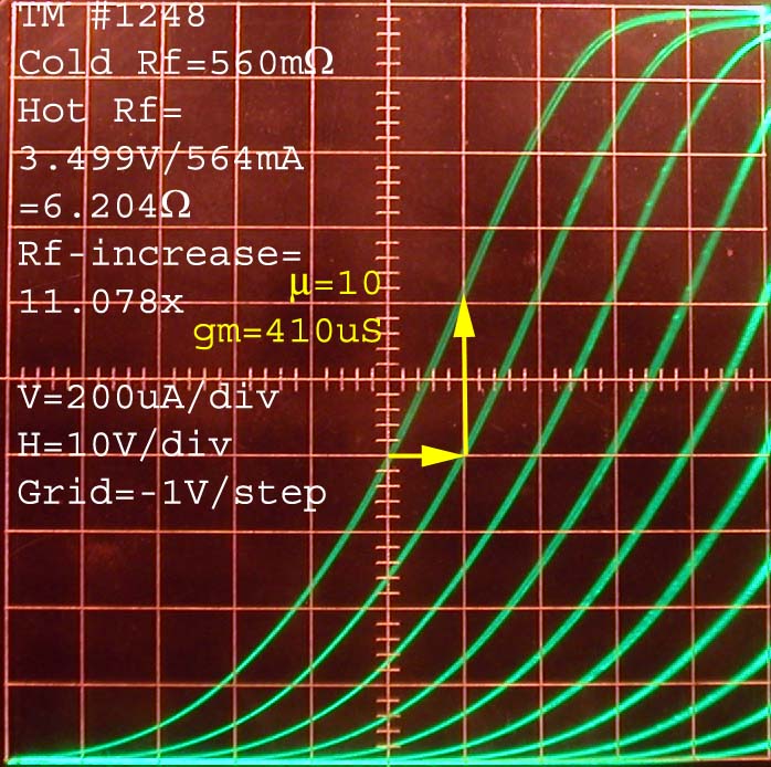
The following two curve families were taken for TM tubes with serial numbers 1247 and 1248. Both tubes have a date code 20W06 stamped on the pressed stem. The "W" in the date code means that the tube was made by Dr. Walz after his friend had passed away.
Temperature limited emission
Unlike coated filaments, that have a low sensitivity to filament voltage, these uncoated pure Tungsten filaments have a very strong sensitivity to filament voltage. The two curve families were normalized with slight adjustments in filament voltage to obtain a current saturation level of 2mA. One explanation for this sensitivity is the very high temperature and low thermal mass of the very fine filaments.
Tungsten filaments are not damaged by operation in the thermally limited regime at the 2mA level shown in the plots. But later coated cathodes can be dammaged by operation at thermal saturation, or with cold cathodes.
Current saturation occurs when the cathode emission is said to be temperature limited, and the anode current curves become horizontal at the top of the plot.
The emission regime below the saturated thermally limited current level is said to be space charge limited. It is this space charge that the grid and anode can control and draw current from. At temperature limited saturated current levels, the grid and anode loose control over the cathode current and gain disappears.
Note that tube #1247 reached 2mA of saturation at the top of the plot with less resistance increase than tube #1248.
The filament resistance required for 2mA saturation suggests 3130K for #1248 and 3320K for #1247.
This difference in running temperatures for the same saturated 2mA current level at the top of the curve families could be explained by slight differences in filament diameter, or even different thermal resistance to the filament attachment wires.
Gains
Early tubes with Tungsten filaments often ran at cathode current levels just below thermal saturation, so the horizontal bend at the top of the curves, where all gain disappears, is an expected part of the curve family behaviour. The operating point is always chosen to be below this limit and biased for optimum match to circuit impedances.
#1247 shows a nominal intrinsic voltage gain mu=6 and a transconductance gm=440uS.
#1248 shows a nominal intrinsic voltage gain mu=10 and a transconductance gm=410uS.
The difference in slope and curve spacing between the two tubes can be explained by differences in grid pitch and spacing with respect to Anode and filamentary Cathode. A mu=10 means that the grid is a more effective shield of the anode field over the cathode than for a mu=6.
From the radio application point of view, tube #1248 with a higher voltage gain and lower operating current would be better suited for the higher impedance input stages, while the higher current tube #1247 with the lower voltage gain, would be better suited for the audio output stage.
Plate resistance
The plate resistance is obtained by dividing the the intrinsic gain mu by the transconductance gm Ra=mu/gm. This yields:
#1247 Ra=1.4k
#1248 Ra=2.4k
The plate resistance is a direct measure of the inverse of the curve slopes.
Somewhat remote cutoff
Note that the 3.4V filament voltage postpones the sharp-cutoff of the curves over a 3.4V*mu range of anode voltages. The positive end of the filament cuts off first and the negative end of the filament cuts off 3.4V*mu volts lower. Only unipotential indirectly heated cathodes have a trully sharp cut-off.
But for combinations of grid and plate voltages that are not cut-off, the shape of the curve is the same as for a unipotential cathode.
A point in the cathode is not cut off if:
Vanode>-Vgrid*mu
Capacitance
Grid to Anode capacitance and Grid to Cathode capacitance:
#1247 Ca-(g+c)=4.5pF Cg-(a+c)=4.6pF
#1248 Ca-(g+c)=4.2pF Cg-(a+c)=5pF
These capacitances point out the need for neutralization in RF amplifier circuits. The measurements were conducted as two terminal measurements with a cold filament. A higher grid-cathode capacitance is expected with the formation of space charge in normal operation.
These award-winning TM tube replicas have special meaning to me. They celebrate the birth of the tube era and the valiant efforts of a tube collector and enthusiast, Dr. Walz, to understand and recreate first-hand this obsolete technology.
Regards,
-Joe
To thank the Author because you find the post helpful or well done.