Tubes operating without anode supply
? Tubes operating without anode supply

Dear friends,
Recently I found an article referring to tube circuits operating without anode supply. The magazine, Electronics by McGraw Hill, December 1952, was too reputable to think of a joke. No wonder since, as the author says, the hot cathode is an appreciable source of energy.
I have never seen before circuits operating in the described conditions. Did they found any practical applications?
Regards, Emilio
--------------------
 ----------------------
To thank the Author because you find the post helpful or well done.
? Worth repeating the experiment!

Hello Emilio, quite obviously I've never heard of an application of this type of circuitry, but the paper is intriguing nonetheless and I think it's worth repeating the experience and see if it works.
I wonder if all 12AU7 will show this behaviour, or if only some models (= years of production?) of some specific brands delivered enough thermal EMF due to metal-metal contacts to operate the circuits.
The circuit that looks more promising to me is number 4, as it has no uncertain components in the schematics (power supply, type of induction coil, Q, etc.). Only resistors and capacitors easily available.
To thank the Author because you find the post helpful or well done.
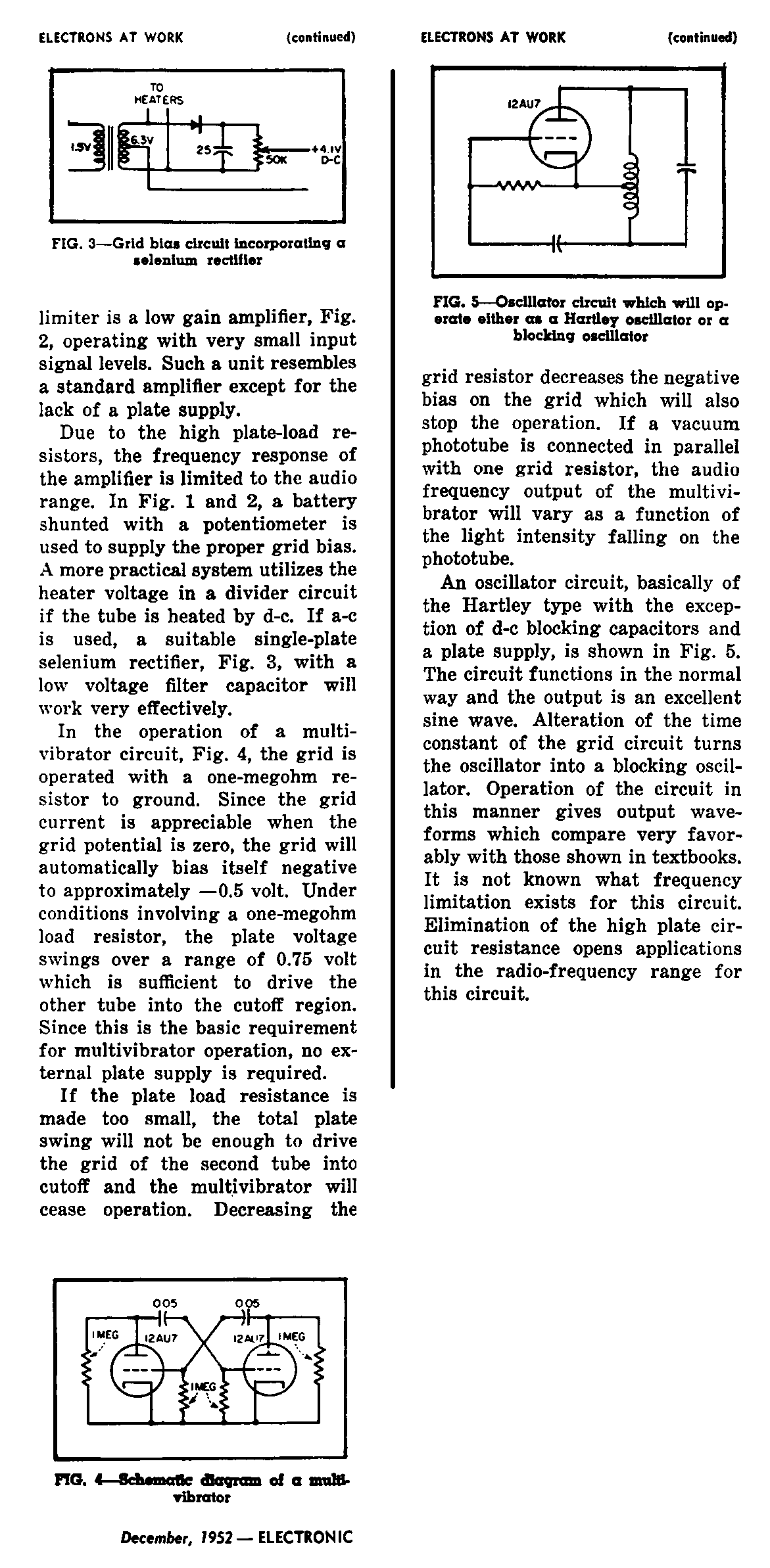
Multivibrator works

Hello Emilio and Marco,
I built the Multivabrator last night, and, at first, it did not work as shown in the schematic of figure 4.
All I had to do to make it work was to reduce the grid leak loads from 1Meg to 22Meg.
The period was over 100ms.
Curve tracing the 12AU7 around this operating region would tell us what are the best values to use.
Marco is right in that only some tubes work. Most important of all is that the tubes have excellent emission. On some tubes, loading the grid with the additional 10Meg DC impedance from the scope probe was enough to kill oscillations.
I made some of the weaker 12AU7 tubes work by increasing heater voltage up to 8V.
The emf source involved here is not the metal-metal thermal emf, which as the article points out adds up to no more than 100mV. The polarity of this small voltage may help or hinder the desired effect.
It is the contact potential of the space charge that produced a -2V grid potential on the strongest 12AU7 I tried.
Interestingly, the contact potential as seen at the plate was always less then half that of the grid. In all cases the anode was more positive than the grid.
I tried higher MU tubes, but none worked, including the 12BZ7, which has about twice the gm of the 12AX7.
These high MU tubes showed zero contact potential at the plate. This is not surprising, considering that a MU=100 means that only 1% of the electric field at the anode is felt by the cathode.
Another intersting thing was that a recently made Electro-Harmonix 12AU7 did not work either.
Perhaps it is possible for a tube to share many aspects of it's operation, without having the same contact potential. Hmm, more than one way to get MU, Gm, and plate current.
The plate efficiency with zero anode voltage may well be the lowest ever attempted in a tube.
The -0.5V contact potential at the 12AU7 anode suggests that more power gain would be possible with a transformer load, than with a resistive load. The impedances involved will probably still be in the Megohm range. It is expected that the grid impedance with a 22Meg load is much lower than 22Meg. Curve tracings will tell.
On a related topic, I remember seeing a 6AL5 tube in an FM Ratio detector with a resistor in series with their heaters to lower cathode temperature in an attempt to reduce the contact potential, or to more optimally bias the diode impedance.
Recently, I built an AM transmitter with "zero anode" voltage using filamentary tubes. But the operation of my transmitter is different than the operation of the circuits in the article above.
In the case of the 1J37B 1.5V filamentary tube in my transmitter, the anode is 1.5V more positive than the negative end of the cathode. It could be said that my anode voltage was actually 1.5V, not 0V. I cheated, just a little bit - this is what so much of engineering is about.
Tube operation did get closely examined in the past, didn't it!
Regards,
-Joe
To thank the Author because you find the post helpful or well done.
? 'Starved' amplifiers
Dear Joe,
you did not loose time indeed! Your experiments confirm that given circuits really worked in this condition. I was not able to find much more about this kind of operation but, since the author gave several application circuits, he should have thoroughly studied all related phenomena. The different results you found among various types of tubes and various manufacturers can be intuitively explained by different geometry of electrode structures. Just in Radio Engineering Handbook from Henney, for years the editor of Electronics, I found some information about operation of a diode with parallel plane electrodes at very low plate voltage, from 10V down to zero. Here are the curves of the potential distribution.

In a space-charge limited emission, at zero plate voltage, the virtual cathode is halfway from cathode and anode. If in a triode the grid is located inside the virtual cathode, it could not operate as control electrode. In high-mu triodes, grids are usually placed very close to cathodes and this could explain why 12AX7 or 12BZ7 do not work at all. Maybe some pentodes, 6AU6 or similar, can be operated as triodes using the screen grid as control electrode, but this only a guess.
I am wondering if these fascinating circuits found any practical applications.
Of course, this is not the sole oddity found in what Electronics referred to as the ‘Electron Art’. I remember to have found low-voltage supply to heaters of some low-level amplifiers of the mid fifties. I can guess that emission fluctuations could arise if very low currents were required from strong emitting surfaces, but I am not sure that this was the true reason.
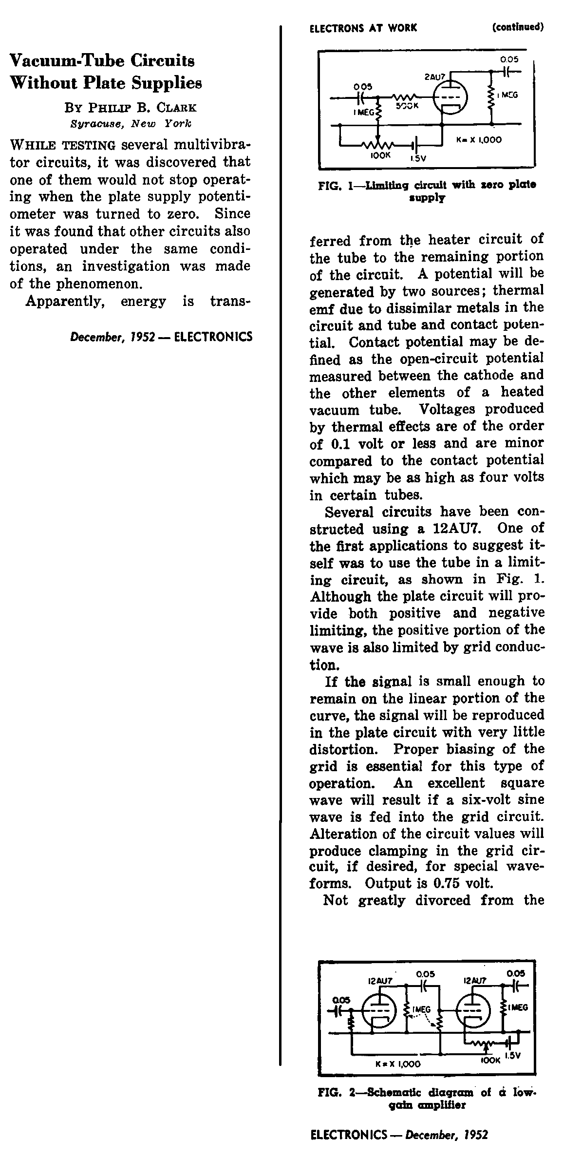
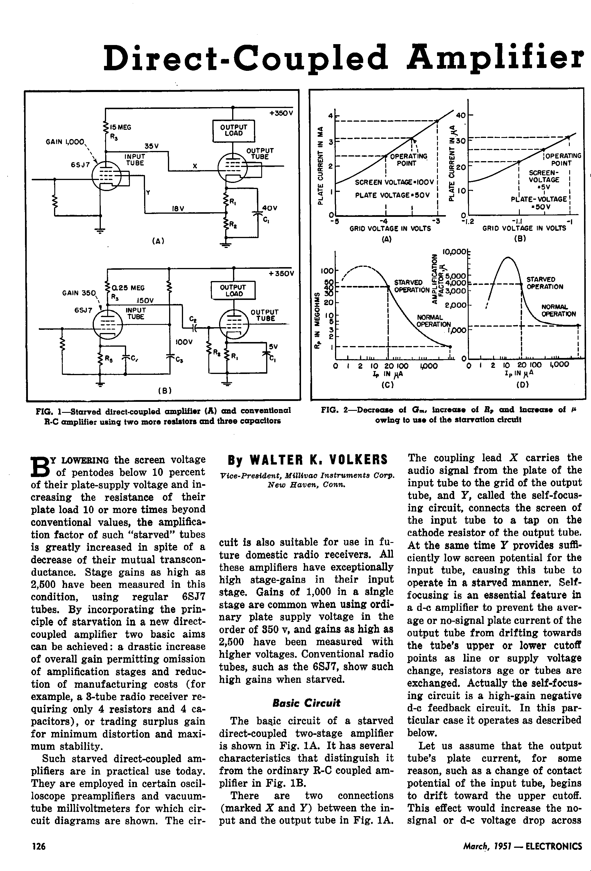
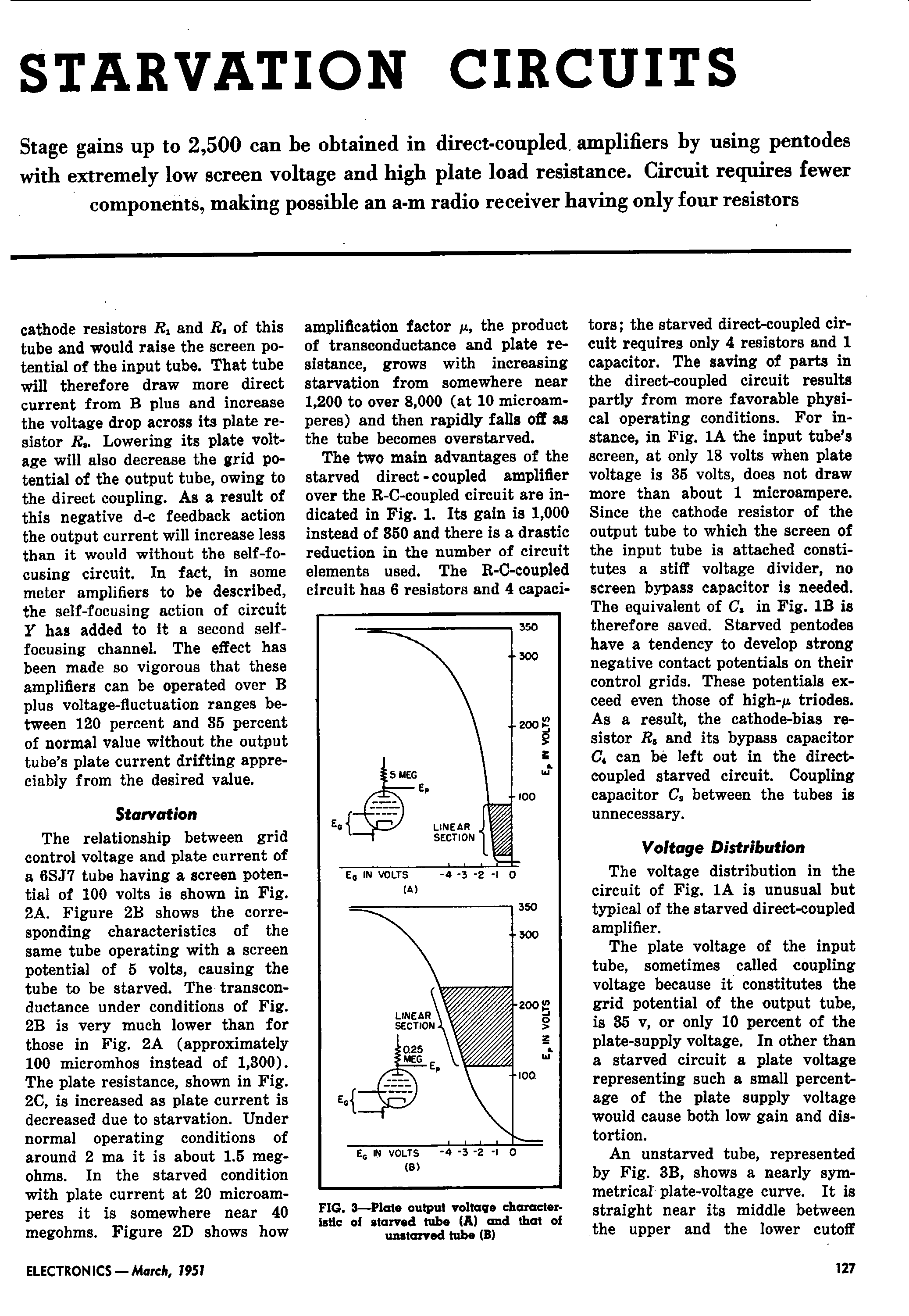
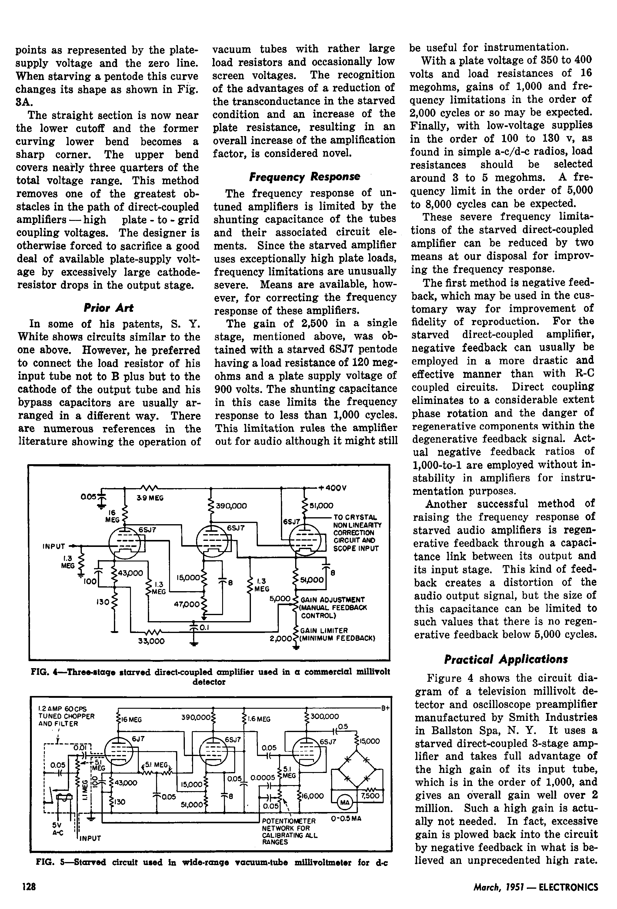
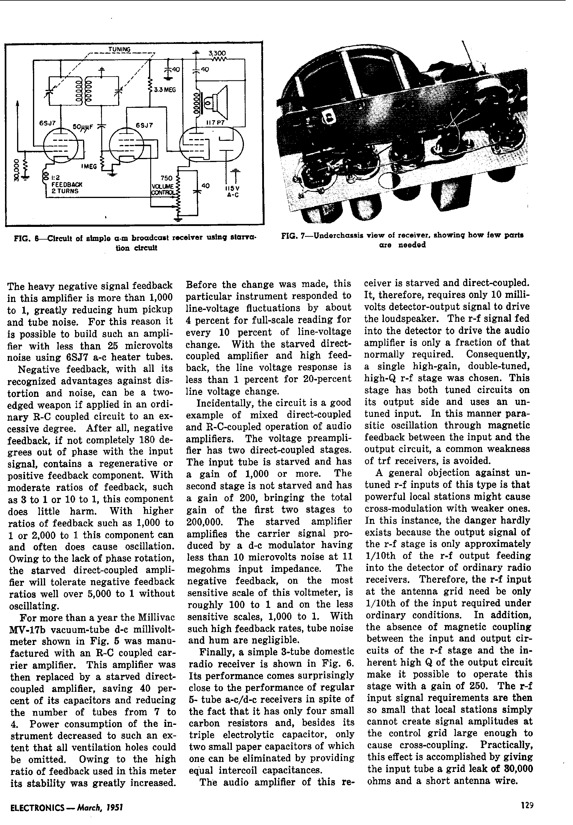
Another odd use of electron tubes was in the ‘starved’ amplifiers (Electronics, March 1951). Here the screen grid voltage was lowered to very few volts and the plate load resistance was greatly increased, resulting in a single stage gain as high as 2500. The article gives diagrams of some amplifiers used in commercial millivoltmeter sets and the diagram of a radio receiver using 3 tubes, 4 resistors and 4 capacitors.
Unfortunately I have not found further developments or documentation about this technique, as for the above odd circuits.
Starvation amplifiers, page 1
Starvation amplifiers, page 2
Starvation amplifiers, page 3
Starvation amplifiers, page 4
Best regards to all, Emilio
To thank the Author because you find the post helpful or well done.
Heathkit EC-1 OPAMP
Dear Emilio,
Thank you very much for the additional information you posted. I will study it soon.
In the mean time, I remembered that Heathkit used a starved amplifier technique to implement their single tube DC opamp in the EC-1 Analog computer. The following schematic was scanned from the EC-1 manual.
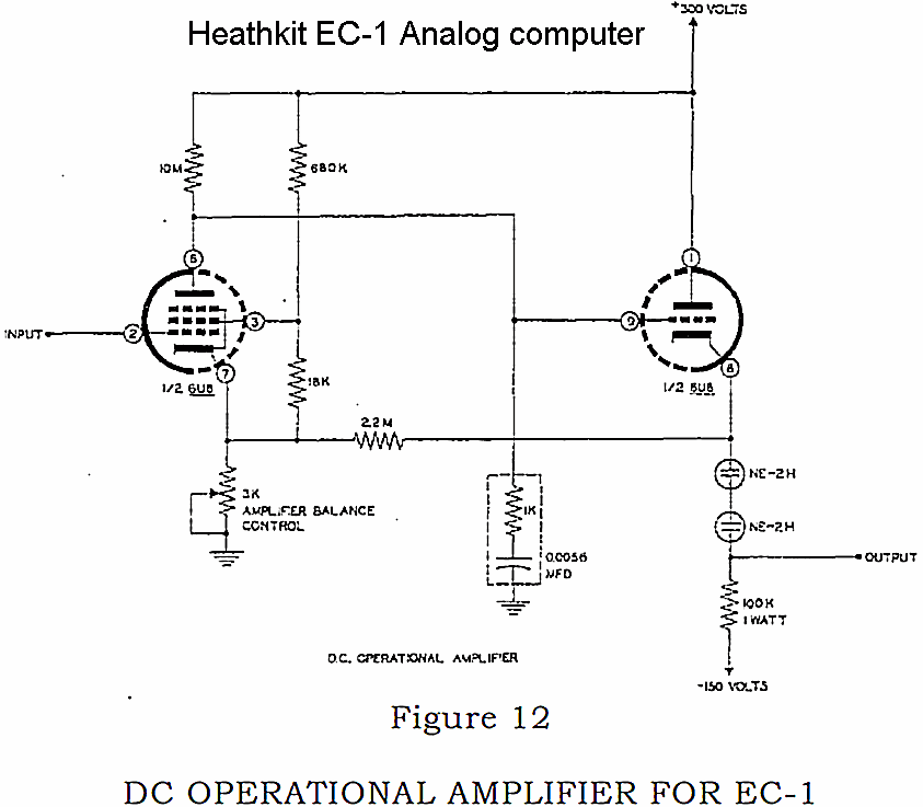
Note that 22Meg resistor between the cathodes is for positive feedback to increase the open loop gain beyond the 700 optimum with starved conditions, up to 1000.
The variable resistor at the pentode cathode trims out DC offset. That is what is meant by "Balance control".
The plate of the starved pentode runs nominally at 120V above the cathode, but swings more than the +/-60Vswing at the output, with a +/-3mA load.
The starved amplifier techniques were used mostly for DC or low frequency use. The emphasis on mu and reduced dependency on Gm and emission were beneficial for long term accuracy in DC applications.
Regards,
-Joe
To thank the Author because you find the post helpful or well done.
Tube sweeps - Multivibrator waves
Hello Emilio and Marco,
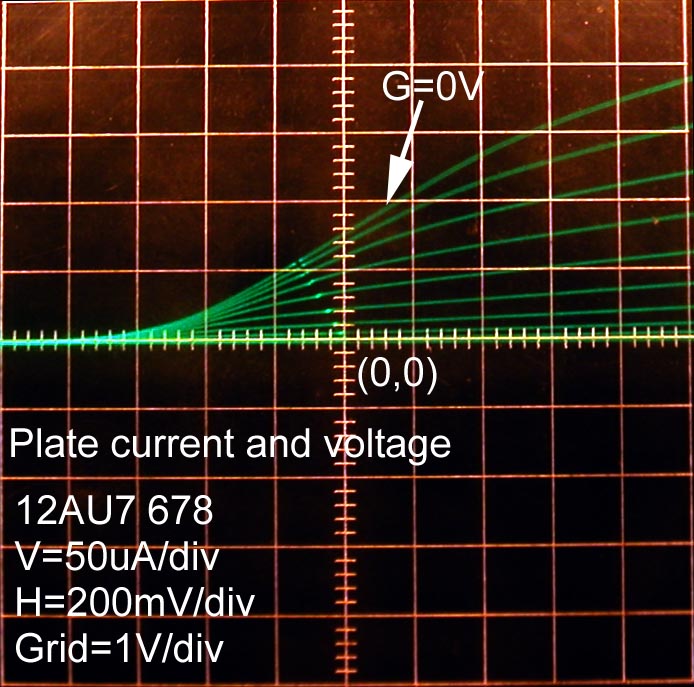
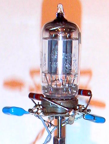
Just to round off my findings, I measured the tube characteristics of a used RCA 12AU7 on the TEK575 curve tracer, and took a couple of scope photos of the multi-vibrator photos.
These six curve tracer photos show plate current and grid current for each of the two halves of a 12AU7. Each triode is identified by it's pins 123 and 678.
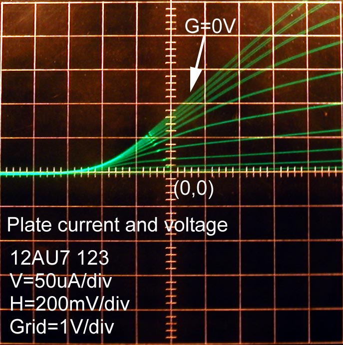
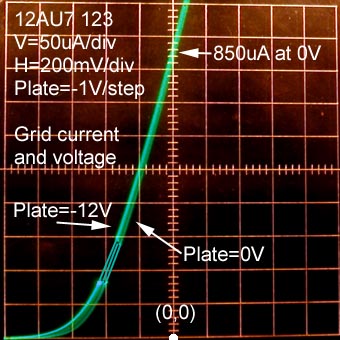

The two following photos show detail at very low grid leak current, down to 1uA.


I made a few DC measurements to supplement these curves.
| Grid 22meg to plate | Grid no load | Plate 1Meg to gnd | |
| triode 123 | 0.92V | 1.1V | 0.46V |
| triode 678 | 0.94V | 1.1V | 0.46V |
These DC measurements were made with a bridge technique, where a DVM measured the difference between a voltage source and the grid. The source was adjusted until the DVM read zero volts. The DVM has an internal impedance of 11MegOhms.
Note that even a 22Meg load is enough to lower the measured grid potential by several tens of mV.
Also note that the grid current at zero volts for the 123 triode is 850uA, with a slope of 1.1kOhms.
The same 123 triode shows an impedance around 100k, when the current is 5uA and the voltage is -0.7V. It appears that current and impedance are roughly proportional.
If this proportionality holds true, then a 22meg grid load to ground, drawing 40nA would set the grid impedance around 10MegOhms.
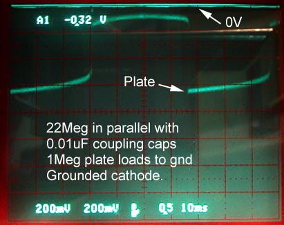
Multivibrator waves
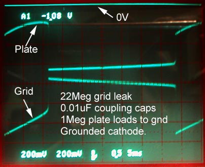
The first photo shows plate and grid voltages with the same multivibrator topology shown in the article above. The only difference is the capacitor and grid load values.
The second photo shows only the plate wave, and the 22Megs are moved to be in parallel with the caps, to cut the grid current bias load in about half. Note the longer period.
All measurements taken with a 10Meg DC scope probe. The added 10Meg load on the grid had a significant effect on the duty cycle of the first photo.
The same 10Meg scope probe load on the grid stopped oscillation altogether on the second photo. This is why there is no grid voltage wave in the second photo.
The photo on the left shows the used RCA 12AU7 tube. The wiring is with the 22Meg resistors in parallel with the 0.01uF caps.
Regards,
-Joe
To thank the Author because you find the post helpful or well done.
'Starved' amplifiers
> I have not found further developments or documentation about this technique
The MIT Radiation Labs (RADAR) series, Amplifiers volume, has a section on low-low-current amplifiers.
But the basics are not magic, just extrapolation.
Voltage gain of an UN-loaded pentode is nearly RL*Gm.
For a given supply voltage B+, and plate idle point "about half-way" up B+, RL should increase in proportion to current decrease.
For most tubes (FETs generally) in their "normal" current range, Gm varies roughly as square-root of current(*). Run half the current, Gm is about 0.7.
Combine these concepts, UN-loaded voltage gain rises when designing for lower current, roughly as square-root of current. 0.5 current is 2X RL and 0.7 Gm, gain increases by 1.4. 1/10th current gives 3X gain.
This also works with triodes except Mu sets an upper limit on voltage gain. Pentode Mu is high and hard to reach.
Circuit resistances get very high. It can be hard to approach "un-loaded" condition.
And specifically: circuit capacitances change very little with current. Gain-bandwidth drops with Gm or as square-root of current. If a tube worked at 1mA has gain of 100 flat up to 50KHz (5MHz gain-bandwidth), then at 0.1mA it is likely to be gain of 300 but gain-bandwidth of 1.6MHz so the flat-gain region extends only to 5KHz.
The article suggests that negative feedback can fix the frequency response; this is untrue. You can trade gain for flat-bandwidth, but the corner frequency will always be lower than normal-current operation.
Low-low-current is valuable when you need high gain at MUCH less bandwidth than normal tubes offer. Ordinary tubes at normal current can do gain*bandwidth over 1MHz.
A meter needs high gain but response can be less than 10Hz.
The Heathkit analog computer wanted good DC gain but did not compute at high speed. Even on fancier analog computers, copying the read-outs took more time than the actual computation. The 0.0056uFd cap gives the op-amp about 2KHz gain-bandwidth; without that cap it would be 300KHz GBW but then the internal positive feedback or some external feedback networks (and patchbay strays) could cause instability.
A full-range audio amp may need gain flat past 50KHz and run 2mA in 47K. An AM radio needs gain but does not want response past 5KHz, we find 270K 470K even 1Meg plate resistors and 200uA-50uA plate currents.
(*) For BJT transistors in their "normal" range, Gm scales directly as current (Shockley's Law), not as square-root. The two trends converge: tubes/FETs at VERY low current lose their root and Gm varies directly with current. This is one reason why the Volkers article shows gain peaking and then declining. However this happens at such low current that it is difficult to show (the MIT book has plots). BJT transistors have a range where Gm rises slower than current, but they are likely to melt at this current density. (There is also an ohmic factor which decreases Gm/Ie even before the melt-down point.)
To thank the Author because you find the post helpful or well done.