Unknown Optical tube
? Unknown Optical tube

Gentlemen, can anyone identify the purpose of this tube?
A part number and maker would be nice too.
The face of the tube looks like an optical surface. What seems like a filament measures about 0.4 Ohms.
The tube has a structure somewhat similar to a Farnsworth image dissector.
This structure could be used to focus or track a point of light in front of the tube.
This exotic optical mystery came tube from www.Fairradio.com. The Fairradio part number is XTUBE-98. If you enter this part number in the search box at Fairradio, you will find the tube for sale for US$20

More pictures attached.
Regards,
-Joe
Attachments:- Mystery_tube-side (102 KB)
- Mystery_tube-top (69 KB)
- Mystery_tube-angle (85 KB)
To thank the Author because you find the post helpful or well done.
Xtube-98 - first only some (intelligent) guesswork.

Dear Joe
I asked a good tube collector and member and he has answered the following to me:
It is some form of photo/imaging tube.
The end window would be probably a caesium coating and the electrode structure a scanning system.
The nearest that I know is this Valve site - with some good pictures.
It would seem to have a very similar construction, but the exact structure and purpose is not known to us.
I hope we will find out one day. I have entered your tube as Xtube-98 so that you can load up your pictures. I will also move your thread to that tube page. I don't know if the base is correct I have chosen.
To thank the Author because you find the post helpful or well done.
Farnsworth Image Dissector?

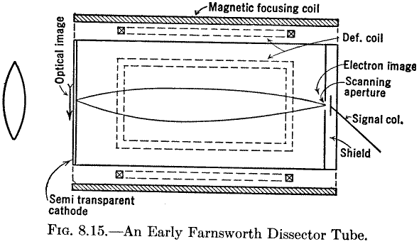
As Joe mentioned, the tube indeed has some resemblance to the outline of an early Farnsworth Image Dissector. A description of the Farnsworth Image Dissector was found in
- Zworkin, V.K.; Morton, G.A.: Television, The Electronics of Image Transmission, Wiley, 1940, pp 230 - 233 and in
- Kerkhof, F.; Werner, Ir.W.: Fernsehen, Einführung in die Physikalischen und Technischen Grundlagen der Fernsehtechnik unter weitgehender Berücksichtigung der Schaltungen, N.V. Philips' Gloelampenfabrieken – Eindhoven, 1951
8.7. Dissector Tube.


Now the 2nd text (in German)
Regards,
Dietmar
To thank the Author because you find the post helpful or well done.
Kerkhof - Translation
Thank you very much for the Dissector material. It includes references about high resolution and contrast performance that I had not seen before.
-------------------------------------
The following is my google-assisted translation of the German language text you posted above, please let me know if I missunderstood the original meaning.
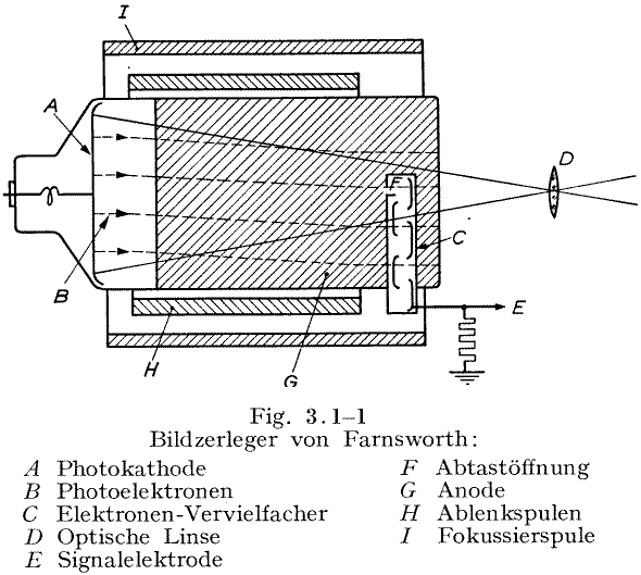
This instrument consists of a so-called photo cathode i. e. a photo-senstivive plate, on which the scene is optically projected, see Figure 3.1 1 [above, in this thread]
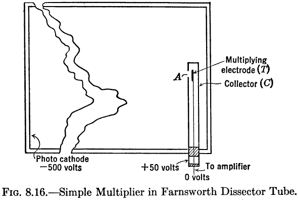
The optical image creates a photoemission of electrons, with a distribution of electrons that is proportional to the respective illuminance in the image. Using an electric field between cathode and anode, the electron image emitted from the cathode moves toward the plate with help in focusing from an axial magnetic. This magnetically focused electron image reaches a multiplier, which has a small opening. When any one electron enters the opening, it strikes a surface with a high secondary emission coefficient, where each striking electron triggers the secondary emssion of 5-10 electrons. These secondary electrons strike again on a subsequent surface, where with the same multiplication occurs. This is repeated several times until finally upwards of a thousand-fold amplification is achieved.
The dissection of the picture is done at the small opening in the electron multiplier. It is thus established that the entire electron image is dissected with the help of deflection coils in two directions perpendicular to each other, so that each time a different picture element appears before the opening in the electron multiplier. Farnworth's Image Dissector shows the advantage of virtually unblemished image decomposition, but it still has the same deficiency as the optical scanning disk dissection, namely the inefficient use of the scene lighting.
At any moment in the Image Dissection, the only captured active electrons are solely those of the dissected (sampled) picture element; and all others are lost.
The poor signal noise ratio is due to the relatively large fluctuations in the statistics in this small number of electrons. The tube is therefore only good to use at high illuminance, i.e. for film transfers. With sufficiently high illumination the Image Dissector can capture exceptional, high-contrast, detailed images.
Kerkhof, F., Werner, Ir.W.: Television, Introduction to the Physical and Technical Principles of television technology taking full account of the circuits, NV Philips' Gloelampenfabrieken - Eindhoven, 1951
Regards,
-Joe
To thank the Author because you find the post helpful or well done.
Diamond Power Spectralty Corp. Dissector
In "Mayers, M.A.; Chipp, R.D.: Closed Circuit Television System Planning, Rider, 1957, pp. 150 -152" a brief description of the image dissector is given, which is used in a Diamond Power Spectralty TV camera.
THE IMAGE DISSECTOR.
The image dissector is a pickup tube of the non-storage type, too insensitive to have found much application in broadcasting, but which has nevertheless been widely used for industrial television.

Figure 3-17 is an outline of the image dissector used in the Diamond Power Specialty Corp. camera.

Figure 3-18 is a photograph of this tube. The scene to be televised is focused on a translucent photocathode, the rear surface of which emits electrons in proportion to the light intensity at each point. The electron image is accelerated toward the anode by a series of ring electrodes and is focused by means of an external focus coil. The complete electron image arrives at a small fixed scanning aperture of sufficient size to pass only those electrons emitted from a small element of the photocathode.
Scanning is accomplished by moving the entire electron image horizontally and vertically, by means of the external deflection coils. As the electron image moves past the aperture, electrons representing the light intensity of each picture element at a specific instant, pass through the aperture, strike a dynode, and generate a signal current that is amplified several million times in an 11-stage electron multiplier. Note that only the electrons emitted during a small portion of the picture-time are collected and used, thus the term non-storage; also, that both the resolution and sensitivity of the tube are controlled by the size of the scanning aperture. Increasing the aperture will permit more electrons to be collected, thus increasing the sensitivity, and will at the same time increase the size of resolvable picture elements (decrease the resolution).
This latter effect is the same as that obtained by increasing the spot-size (defocusing) in the scanning beam of a picture tube. In one industrial version of the image dissector, known as the Utilicon, the aperture is a .030-inch square hole, which represents a resolution of approximately 300 lines.
Some facts of interest to the user are:
(a) Resolution capability: as noted above, ap proximately 300 lines.
(b) Required illumination: approximately 300 foot-candles of scene illumination for a good picture, using an f/1.4 lens. Lower light values have produced usable pictures.
(e) Spectral response: two types of photocathodes are available, as shown in Fig. 3.19. Both include the visible portion of the spectrum, but one peaks in the infrared region; the other in the ultraviolet region.

(d) Scanned image: 2.5-inch diagonal, requiring larger lenses than are used for 35 mm or 16 mm applications.
(e) Environment: this tube is rugged in construction and the camera using it will operate between -180C (00F) and 660C (1500F).
(f) Power supply requirements: a single – 2,300-volt supply, with appropriate voltage dividing networks, will supply the tube itself. A normal B+ supply feeds the external coils.
(g) Life: this tube has inherent long life, one reason being that there is no heated cathode required to generate electrons for a scanning beam. The Utilicon is guaranteed for one year; reportedly some tubes have been in service for as many as 10.
(h) Cost: $600.
Regards,
Dietmar
To thank the Author because you find the post helpful or well done.