Unknown Resistors
? Unknown Resistors

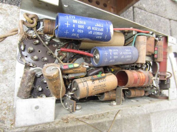
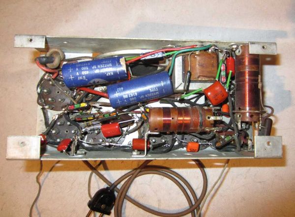
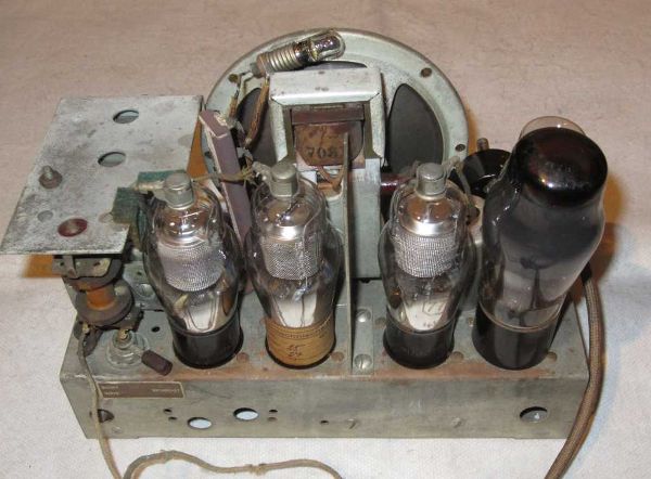
I'm presently restoring a radio that was built in the US and marketed in France by Bollack et Cie, L.; Neuilly, Paris in the mid-thirties : "Radio Trust"
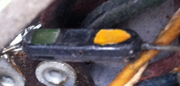
While the majority of the components used in this set are typical for US radio sets of that era, some of the resistors are completely different from everything I've ever encountered in a radio set. That's what they look like:

Somehow they resemble Mica-capacitors with their typical color dots ... but they are resistors. The dimensions are:
Width: 5mm, Thickness: 3.5 mm. Length: 20mm
The set contains resistors showing 3 different color codes. Assuming that the dots have to be read in the direction of the pointed color dot, we have:
- blue / green / red, sitting in the cathode grounding path of the detector tube '75'

Having in mind the typical resistor color codes, one might assume a value of 6.5 kOhms. I measured a value of 10.5 kOhms. This is about 50% above the indicated value - but some composite resistors (I assume this is a composite resistor) have this 'geriatric' problem of becoming progressively more resistive as they get older.
- red / green / orange, sitting in the screen grid supply of the convertor tube '6A7'

Following the same line of reasoning, one might expect a value of 25 kOhms. I measured 56.2 kOhms.
- green / blue /yellow, sitting in the AVC line. As a matter of fact, there are 2 resistors with this code. On one of them the color looks more orange, on the other more yellow. Since both are sitting in the AVC line and since resistors in this part of the circuit are usually very high ohmic, I assumed that yellow is more likely than orange.
If this assumption is correct. we should have 560 kOhms. I measured 2.35 MOhms on one and 2.47 MOhms on the other. Now that really looks way out of the color code!
This brought me to another idea: Maybe the color code has to be read in the opposite direction? This would mean that the last resistor should have a value of 3.6 or 4.6 Mohms? On the other hand this wouldn't make any sense for the above mentioned resistors.
Is there anybody around who knows the answer? Thanks in advance for any suggestions!
Harald
To thank the Author because you find the post helpful or well done.
Unknown Resistors
From all of the information I have, you are reading the codes correctly. This type of resistor does go very high in value if the radio has not been operated to dry out the moisture. If you want to keep them in the radio, they will probably return to a more normal resistance after the radio is operated for several days. You could also take out the resistors and put them in an oven for a few hours. If you dry them out, I suggest coating them with clear fingernail polish or something similar to seal out the moisture.
To thank the Author because you find the post helpful or well done.
Unknown Resistors - temperature treatment
Hello Jay,
thanks a lot for your truly enlightening reply! I was wondering why the value of the AVC resistors increased so much more than that of the cathode and screen grid resistors. Now it is clear. The AVC series resistors do not see any significant current flow. No current-flow -> no heating. I will remove one of them from the chassis and put it into the oven for a while to see by how far I can reproduce the original value. Varnishing them after the temperature treatment sounds like a good strategy if one wants to preclude future moisture penetration.
To thank the Author because you find the post helpful or well done.
Unknown Resistors
I think a temperature of about 75C will be OK for drying the resistors. I have seen problems with the paint codes discoloring at about 100C but that will depend on the quality of the paint. Also the resistors have sometimes been damaged too much to recover. If the case is cracked due to swelling of the resistor element, the resistor will probably not be usable.
Volume and tone controls also have the problem of drifting to a high value when a radio has been stored in a high humidity environment. They can also benefit from some time in an oven if the resistance is far above the original value.
To thank the Author because you find the post helpful or well done.
Unknown Resistors Or Capacitors?
I'd check that they are not just capacitors that are gone leaky.
Look at what they connect and decide if a capacitor or resistor.
- Anode loads
- Screen Grid loads
- Control Grid leaks (highest)
- Cathode loads (lowest).
- HT dropping / smoothing.
- Very occasionally there might be a resistor across a coil to damp the Q, but rare.
To thank the Author because you find the post helpful or well done.
Unknown Resistors Or Capacitors?
I know what you mean. These components bear a certain similarity to the typical US Micamold capacitors. When I first revised this radio set, this similarity confused me too.

But the components we're talking about here are definitely resistors.
This one for example is connected between the cathode of the demodulator/AF-preamp-tube '75' and ground. It has a 10µF electrolytic connected in parallel.

To thank the Author because you find the post helpful or well done.
Unknown Resistors
I found a patent for manufacturing these resistors.
If you do a search for Micamold Resistors on Google, you will find pictures and other forum threads about them. Some collectors think they are wirewound and only fail open but the patent is for carbon resistors.
Some collectors have a low opinion of Micamold and replace anything with that name on it. I have found a number of Micamold capacitors with water in them. Bad ones are easy to find because they will have a voltage across them after being shorted. I think I have seen as much as 300mV but would replace any non-electrolytic capacitor that has more than 50mV after shorting.
To thank the Author because you find the post helpful or well done.
Unknown Resistors
On an Atwater Kent 308 I did change one Micamould silver mica (SM) tracker: it measured 100M Ohm but being as I have never measured a SM that didn’t show G Ohms, at hundreds of volts, I wasn’t happy about it. Some of these have had bad press on US forums and for larger values are apparently not even mica but wax paper. This one was SM though once I had taken it apart. I could see nothing wrong inside but the first and last plates were mounted on cardboard so perhaps it was this that was causing the minor leakage.
Gary
Attachments:- Micamould capacitor (83 KB)
To thank the Author because you find the post helpful or well done.
Unknown Resistors
Yes, there are US paper dielectric capacitors in the mica style moulded cases. It's news to me that the package was also used for resistors.
The paper dielectric is impregnated with oil on some hermetic types, but otherwise a soft waxy paraffin like compound similar to Vaseline / petroleum jelly, which eventually absorbs water, then the capacitors are leaky. The card tube types were known at the time to have only about 10 year life. Some of the metal cased tubular ones are nearly OK after 60 years, others had maybe 15 year life.
Decent mica caps wiith no card last forever, even if un-encapsulated.
To thank the Author because you find the post helpful or well done.
Unknown Resistors Or Capacitors?
It's normal though to put low value ceramic or mica capacitors across electrolytic capacitors where RF needs to be decoupled. Some RF equipment might have four different capacitors from 100pF to 10uF on the same point!
However I agree these particular ones seem to be resistors. I can't see how damp makes the resistance rise, usually it lowers it. High value resistors made of carbon composition (carbon & clay mix), go high. Some kinds of cathode resistors (not wire wound) can go low, an unfortunate combination. Wire wound can go high due to oxidising.
To thank the Author because you find the post helpful or well done.
Unknown Resistors

Guten Tag Herr Giese
Auch mir sind diese Widerstände erst in einem Gerät begegnet - einem Emerson 250AW von 1933 (Exportversion)
Im Gegensatz zu den in gleicher Zeit üblichen Leistungswiderständen im Metallgehäuse mit Chassismontage haben sich diese Widerstände ebenso wie der auf dem Chassis stehenden Leistungswiderstand in meinem Fall als unauffällig gezeigt. Das trotzdem dieses Gerät eine schlechte Lagerung über Jahrzehnte wohl in einem offenen Estrich hinter sich hatte.
Viele Grüsse, Walter Haring
To thank the Author because you find the post helpful or well done.
Unknown Resistors Or Capacitors?
It does seem like water in a composition resistor might lower the value but I think it makes the resistance element swell. Expanding the resistance element separates the resistive material and makes the resistance increase. The water is not as conductive as the resistance material.
I have seen some resistors of the Micamold type where the resistance element has expanded enough to split the housing.
To thank the Author because you find the post helpful or well done.
Resistor failure mechanisms
Solid state physics is a complicated matter and the long time behaviour of crystalline compounds is difficult to predict - in particular when gases or liquids diffuse into the compound. As Jay said quite rightly, the intrusion of water along with swelling of the resitive element can increase the resistance value. Crystallites will have less 'intimate' contact with their neighbours, and their surface properties will change as they are covered in H2O dipole layers. Even gases penetrating into the crystalline compound can change electric properties if this occurs over extended periods of time.
Surprising to hear that the 'Micamold' resistors in Walter Haring's EMERSON 250AW are still within their tolerances. Some people are just lucky. Or did the manufacturer change the recipe of the resistors at some point?
In the meantime I ran the following simple test. Assuming that I read the color codes correctly, I shunted the 4 Micamold resistors in my radio using resistors that would put the value back to what it should be. The result: the radio played like before, just the AVC time constant became smaller. Not surprising since there the values had really increased dramatically.
That' what I call a clever circuit design!
To thank the Author because you find the post helpful or well done.
Resistor failure mechanisms
Or just shows how tolerant valves are to changes in component values. But they dont like caps that leak to the grid as we know.
Gary
To thank the Author because you find the post helpful or well done.
Resistor failure mechanisms
After unravelling the wire ends of the four Micamold resistors, meticulously wound through the holes of the soldering lugs, I followed the procedure proposed by Jay Kinnard.
The resistors were put into an oven, and the temperature was set to 75C. The heating ramp was approx. 10C/min. The resistors were then 'baked' for about 1 hour, and afterwards allowed to cool down very slowly.
Unfortunately, the resistance values had dropped by about 1% only. But they had changed in the right direction! I'm thinking now about repeating the whole procedure at a somewhat higher temperature.
In the process I discovered something interesting: On the rear side the resistors look like this:

I had not seen this before, since the manufacturer had soldered in the resistors in such a way, that to somebody looking underneath the chassis they would show their color code - not their brand mark.
To thank the Author because you find the post helpful or well done.
Results of the latest thermal treatment
After long hesitation I ventured to run another thermal treatment test at elevated temperature.
The resistors were now baked at 100C over a time span of 1.5 hours. After that the color dots looked somewhat different and part of paint fell off the resistor body.
The results:
Color code --- Start value --- pesent value after 100C baking
6.5k -> 10.5k -> 10,6k
25k -> 56.2k -> 56.2k
560k (#1) -> 2.35M -> 2.0M !
560k (#2) -> 2.47M -> 2.2M !
Conclusion:
(i) The value of first two resistors changed very little.
(ii) The values of the last two resistors dropped significantly. Unfortunately they are still far away from those indicated by the color code.
I reckon there is little hope that the original values can be restored. Fortunately the radio is running nicely the way it is. So I'd better stop here.
Thanks for your helpful contributions!
Harald
To thank the Author because you find the post helpful or well done.
Results of the latest thermal treatment
Thank you for providing useful information there.
Gary
To thank the Author because you find the post helpful or well done.