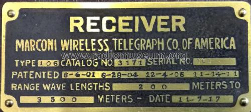
106 Receiver 1st version 7 Binding Posts
Marconi Wireless Telegraph Co. of America
- Country
- United States of America (USA)
- Manufacturer / Brand
- Marconi Wireless Telegraph Co. of America
- Year
- 1915/1915
- Category
- Detector-Radio (Crystal or diode, without tubes/transistors)
- Radiomuseum.org ID
- 103737
-
- alternative name: American Marconi || Marconi, American
- Brand: Marconiphone


Collection privée (réf.: 714, 1873, 2375)

Collection privée (réf.: 714, 1873, 2375)
Ebay Item Number: 161319608609

Ebay Item Number: 161319608609

Ebay Item Number: 161319608609
Ebay Item Number: 161319608609

Ebay Item Number: 161319608609
Ebay Item Number: 161319608609

Ebay Item Number: 161319608609
Ebay Item Number: 161319608609

Ebay Item Number: 161319608609

Ebay Item Number: 161319608609

Ebay Item Number: 161319608609
Ebay Item Number: 161319608609

Ebay Item Number: 161319608609

Collection privée (réf.: 714, 1873, 2375)
Click on the schematic thumbnail to request the schematic as a free document.
- Main principle
- Crystal or Solid State Detector
- Wave bands
- Broadcast (MW) and Long Wave.
- Power type and voltage
- Dry Batteries
- Loudspeaker
- - For headphones or amp.
- Material
- Wooden case
- from Radiomuseum.org
- Model: 106 Receiver [1st version 7 Binding Posts] - Marconi Wireless Telegraph Co.
- Shape
- Tablemodel, Box - most often with Lid (NOT slant panel).
- Dimensions (WHD)
- 23 x 12 x 11 inch / 584 x 305 x 279 mm
- Notes
-
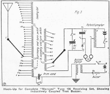
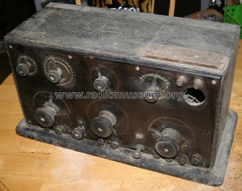
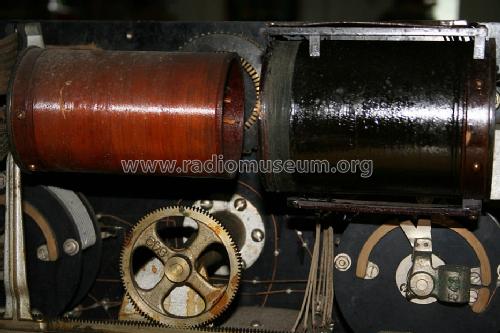
The Marconi 106 receiver covered 200-3500 meters and was used primarily for marine applications.
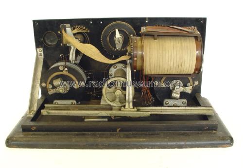
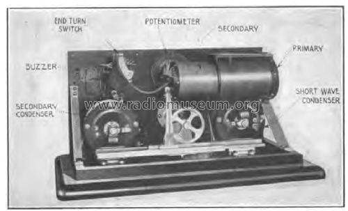
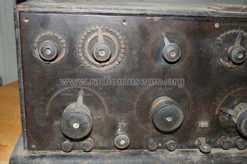
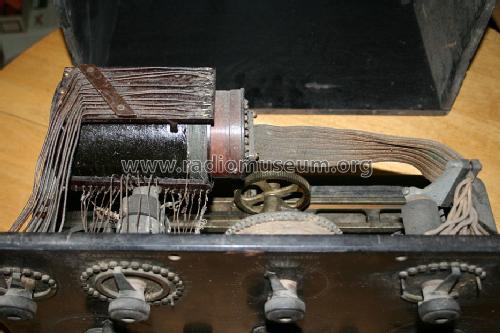
Production of the Marconi 106 started at the Marconi Aldene plant in New Jersey. The 106 was equipped with two types of crystal detectors. A cerusite crystal and a carborundum. The cerusite was more sensitive but the carborundum was more stable in shipboard applications. The appropriate detector material for conditions was then placed in the single detector crystal holder mounted on the front panel. This first version of the 106, had a nickel plated brass buzzer cover held on by two screws. This buzzer was replaced with a buzzer with a twistoff cover in mid-1915 in the first 106 design change.
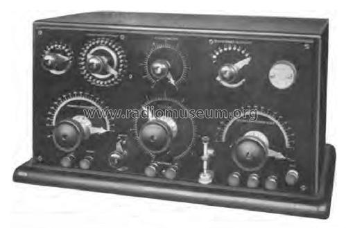
The 1st version had 7 binding post along the lower bottom of the front panel. Two pairs were located to the left of the detector and three more located to the right. The first four pairs were assigned 1-4 but the bottom of the detector was assigned number 5. The three post to the right of the detector were assigned 6 ,7 & 8 and 9. The center post was assigned both 7 & 8 because it was the common post for the battery connections for both the buzzer circuit and the crystal detector bias circuit.
A dry battery was used to power the buzzer to adjust crystal detector and bias the carborundum detector.
- Net weight (2.2 lb = 1 kg)
- 14.5 kg / 31 lb 15 oz (31.938 lb)
- Source of data
- -- Collector info (Sammler)
- Mentioned in
- Radiola, the golden Age of RCA (page 48-52)
- Literature/Schematics (1)
- Vacuum Tubes in Wireless Communication, Elmer E. Bucher, 1918, p.15
- Literature/Schematics (2)
- June, 1917 Electrical Experimenter magazine page 112
- Author
- Model page created by John Koster. See "Data change" for further contributors.
- Other Models
-
Here you find 33 models, 33 with images and 3 with schematics for wireless sets etc. In French: TSF for Télégraphie sans fil.
All listed radios etc. from Marconi Wireless Telegraph Co. of America
Collections
The model 106 Receiver is part of the collections of the following members.
Literature
The model 106 Receiver is documented in the following literature.