Frequency Calibrator FCC90B
Bud Radio Inc.; Cleveland (OH)
- Produttore / Marca
- Bud Radio Inc.; Cleveland (OH)
- Anno
- 1960 ??
- Categoria
- Strumento da laboratorio
- Radiomuseum.org ID
- 207005

Clicca sulla miniatura dello schema per richiederlo come documento gratuito.
- Numero di tubi
- 2
- Principio generale
- Trasmettitore
- Gamme d'onda
- Gamme d'onda nelle note.
- Tensioni di funzionamento
- Alimentazione a corrente alternata (CA) / 110 Volt
- Altoparlante
- - - Nessuna uscita audio.
- Materiali
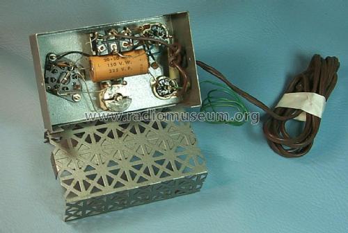
- Mobile di metallo, valvole visibili
- Radiomuseum.org
- Modello: Frequency Calibrator FCC90B - Bud Radio Inc.; Cleveland OH
- Forma
- Soprammobile con qualsiasi forma (non saputo).
- Dimensioni (LxAxP)
- 3 x 4.75 x 4 inch / 76 x 121 x 102 mm
- Annotazioni
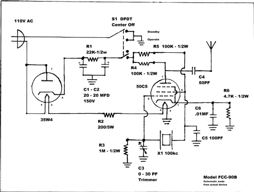
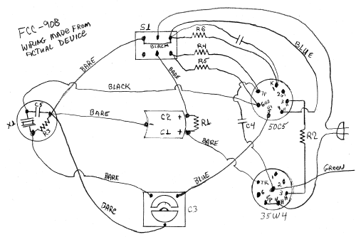
- This is an independent device to generate a marker signal every 100 kHz through the radio spectrum. The purpose is to verify and/or calibrate the frequency dial pointer of a radio receiver. The device has a trimmer adjustment to allow it to be zero beat to a known frequency standard (like WWV) which then produces an accurate marker across the dial from the harmonics generated from the 100 kHz crystal. The range of this device starts at 100 kHz through at least 60 MHz with markers every 100 kHz and much stronger markers every 1 MHz. No connection to the receiver is necessary, only a loose coupling of the output wire to the antenna of the radio. The power switch has two positions to place it in a standby state, and an operating state. The circuit is powered directly from the line input using no transformer. The size dimensions include the height of the tubes.
- Peso netto
- 1 lb 1 oz (1.063 lb) / 0.482 kg
- Autore
- Modello inviato da Walter (Mike) Meek. Utilizzare "Proponi modifica" per inviare ulteriori dati.
- Altri modelli
-
In questo link sono elencati 15 modelli, di cui 13 con immagini e 2 con schemi.
Elenco delle radio e altri apparecchi della Bud Radio Inc.; Cleveland (OH)
Collezioni
Il modello Frequency Calibrator fa parte delle collezioni dei seguenti membri.