Dual Trace Oscilloscope 540
BWD Electronics Pty Ltd.; Mulgrave, Victoria
- Land
- Australien
- Hersteller / Marke
- BWD Electronics Pty Ltd.; Mulgrave, Victoria
- Jahr
- 1976
- Kategorie
- Service- oder Labor-Ausrüstung
- Radiomuseum.org ID
- 322894
Klicken Sie auf den Schaltplanausschnitt, um diesen kostenlos als Dokument anzufordern.
- Anzahl Röhren
- 1
- Röhren
- Anzahl Transistoren
- Halbleiter vorhanden.
- Halbleiter
- Betriebsart / Volt
- Netz und Power Jack, meist mit Batterie oder Akku / AC: 98-135 V & 195-270 V. DC: 20 V-30 Volt
- Lautsprecher
- - - Kein Ausgang für Schallwiedergabe.
- Material
- Metallausführung
- von Radiomuseum.org
- Modell: Dual Trace Oscilloscope 540 - BWD Electronics Pty Ltd.;
- Form
- Schweres Gerät für Militär oder Industrie (Boatanchor > 20 kg).
- Abmessungen (BHT)
- 170 x 153 x 418 mm / 6.7 x 6 x 16.5 inch
- Bemerkung
-
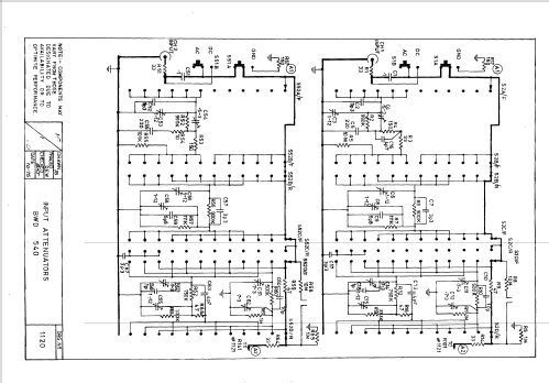
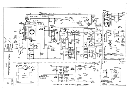
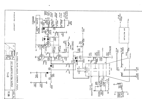
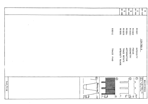
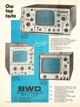
The BWD 540 field portable DC to 100MHz, 5mV to 20V/div dual channel oscilloscope provides the high performance demanded of a laboratory instrument with the advantage of lightweight and optional battery operation of a portable instrument. The BWD 540 has the features and performance to make accurate measurements with ease. A well laid out panel and a large high intensity 8 x 10 cm CRT simplifies operation learning time and makes for easier operation.
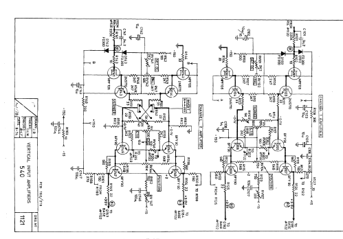
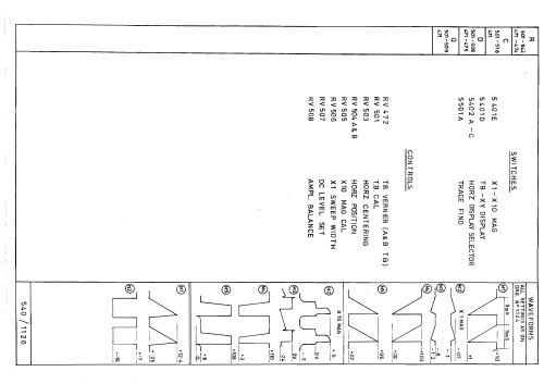
Several features make this oscilloscope unusually versatile. A times 5 gain amplifier for Ch. 1 increases the sensitivity to 1mV/div without losing the dual trace facility that cascade operation via cable patching causes. X-Y operation is phase corrected to give ten times the measuring range than is usually provided.
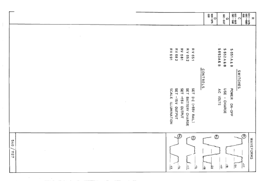
Polarity inversion and a vernier are also included for the X input.Alternative power input requirements give the 540 a ‘go anywhere’ low voltage, as operation is possible from AC sources, low voltage DC or an optional battery pack. The battery charger is incorporated as standard and the battery pack may be added at any time, carried separately and the oscilloscope may even be operated remotely from it by an extension cable.
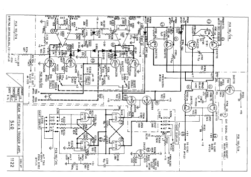
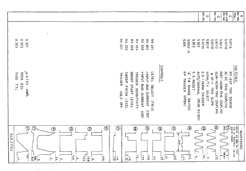
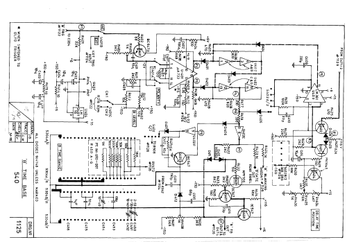
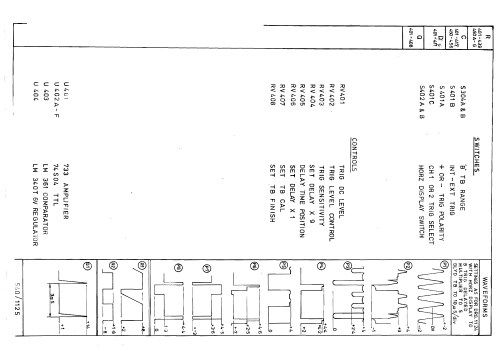
The two time bases feature wide operating range from 5n sec/div down to 5sec/div for the main time base and 1 sec/div for the delayed time base. Triggering extends to beyond 100MHz for 1 div deflection and both time bases have individual trigger selection of both source and polarity. Internal trigger take off is taken before the position controls but after the vernier and polarity controls. This
ensures the trigger level control setting is always related to the displayed signal amplitude but not its position on the CRT. It also means the Ch. 1 signal output is always proportional to the Ch. 1 display.
An additional trigger facility provided for the main time base is a video sync. separator for stable T.V. line or frame lock. This feature may also be used in communication work to lock modulated RF signals to the modulation envelope. For modulated signals and complex digital words, a variable trigger hold off operates on all time base speeds.
Weight of 19kg includes battery pack.
- Nettogewicht
- 19 kg / 41 lb 13.6 oz (41.85 lb)
- Literaturnachweis
- - - Manufacturers Literature (Service Manual, Issue 15)
- Autor
- Modellseite von Gary Cowans angelegt. Siehe bei "Änderungsvorschlag" für weitere Mitarbeit.
- Weitere Modelle
-
Hier finden Sie 25 Modelle, davon 19 mit Bildern und 6 mit Schaltbildern.
Alle gelisteten Radios usw. von BWD Electronics Pty Ltd.; Mulgrave, Victoria