Tube Tester 224
Conar Instruments; Washington (DC)
- Pays
- Etats-Unis
- Fabricant / Marque
- Conar Instruments; Washington (DC)
- Année
- 1978
- Catégorie
- Appareils de mesure et de dépannage (matériel de labo)
- Radiomuseum.org ID
- 135381
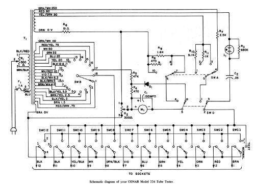


Cliquez sur la vignette du schéma pour le demander en tant que document gratuit.
- Gammes d'ondes
- - sans
- Tension / type courant
- Alimentation Courant Alternatif (CA) / 120 Volt
- Haut-parleur
- - - Pas de sortie basse fréquence
- Matière
- Matériaux divers
- De Radiomuseum.org
- Modèle: Tube Tester 224 - Conar Instruments; Washington
- Forme
- Modèle de table profil bas (grand modèle).
- Dimensions (LHP)
- 15.25 x 10.5 x 6.13 inch / 387 x 267 x 156 mm
- Remarques
-
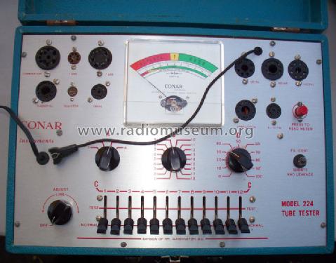
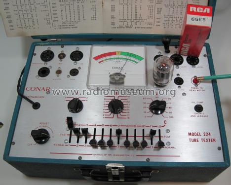
Conar 224 Tube Tester, 11 valve holders, one instrument, neon lamp, manual test voltage selection.
- Source
- -- Original-techn. papers.
- Auteur
- Modèle crée par d'un membre de A. Voir les propositions de modification pour les contributeurs supplémentaires.
- D'autres Modèles
-
Vous pourrez trouver sous ce lien 19 modèles d'appareils, 19 avec des images et 10 avec des schémas.
Tous les appareils de Conar Instruments; Washington (DC)
Collections
Le modèle Tube Tester fait partie des collections des membres suivants.
Contributions du forum pour ce modèle: Conar Instruments;: Tube Tester 224
Discussions: 1 | Publications: 1
I wanted to share some information with the Radio Museum about the Conar 224 tube tester that may be of value to visitors to your website, especially those that may have need to repair an inoperable Conar 224 tube tester. Please note this information has to do with the particular Conar 224 tube tester I have in my possession, condition may vary with other Conar 224 tube testers in circulation.
I purchased a Conar 224 tube tester on eBay about 6 months ago, it was advertised in working condition, the outside condition of the device was pristine, like new, however after receiving the device it failed to function properly, the seller stated that he/she had tested various tubes with it and it was in working condition, this was far from the truth regarding the tube tester condition.
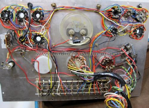
When I received the tube tester I proceeded to thoroughly inspect the device electronically and found several defects that needed to be addressed. The tube tester was originally a kit version that someone had assembled.
The first defect I found was .... when the transformer was constructed, or when the assembly manual was written for the Conar 224 tube tester there was an error with secondary transformer wire leads identification, specifically the wire lead that connects to position 7 of the rotary switch SW39.
According to the assembly manual and schematic the transformer wire lead that’s supposed to connect to position 7 of the 18 position rotary switch SW39 is identified with the color code BLK/BRN (manual revision 179-KM-224), this is incorrect, the actual wire lead color from the transformer for position 7 of the rotary switch is actually GRN/BLK. Obviously this wire color identification problem may have been overlooked/missed when the assembly manual was written and published, perhaps Conar Instruments corrected this in a later revision, but I felt that it was prudent to pass this information along to anyone that owns a Conar 224. For the record, my Conar tube tester has no single primary or secondary transformer wire lead exiting the transformer with the color combination of BLK/BRN that came with the kit I have in my possession.
The second defect I found had to do with the 18 position rotary switch SW39. The actual switch assembly was 180 degrees out of alignment, I suspect that someone assembled rotary switch incorrectly either at the manufacturer, or the kit builder tampered with it, it had been disassembled and reassembled incorrectly, causing the switch contact points to be 180 degrees out of alignment, thus element voltages would be incorrect for each position of the rotary switch, obviously, this would more than likely cause damage to vacuum tubes under test when applying incorrect voltages to the tubes.
Whomever owns a Conar 224 tube tester should inspect the rotary switch thoroughly to be absolutely sure the rotary switch SW39 was assembled correctly before wiring it and applying any power to the tube tester. Keep in mind that depending on how one views rotary switch SW39.....from front, back, right side up, or down, of the control panel. One could easily become confused and assume that rotary switch SW39 was assembled incorrectly by the manufacturer, or it was tampered with by a kit builder who decided to disassemble and reassemble SW39 with it being with it 180 degrees out of alignment, when in fact it was OK the way it was.
The third defect has to do with two secondary transformer wire leads. Two of the secondary wire leads were exactly the same color of orange. The schematic states that one lead should be orange and the other should be brown, however, it was impossible to distinguish one from the other. The only way to be absolutely sure of which wire is which, is to check them with a volt meter. Given the circumstances the two transformer wire leads could be easily reversed if voltages weren't checked. Age could have also caused the wire lead colors to fade, regardless, it's easy to confuse these two wire leads.
Obviously, the tube tester I acquired might not be the norm and I just wound up with one that had these issues, however, whomever might work on one of these tube testers should keep the aforementioned in mind just in case other tube testers got through with these defects.
After correcting the defects the tube tester worked perfectly.
I hope this information may be of some use to user of this website. Feel free to edit the context of my email.
Bob Krueger, AB7CQ
Tombstone, AZ 85638
Mike Edwards † 25.10.21, 10.Apr.21