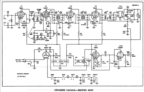
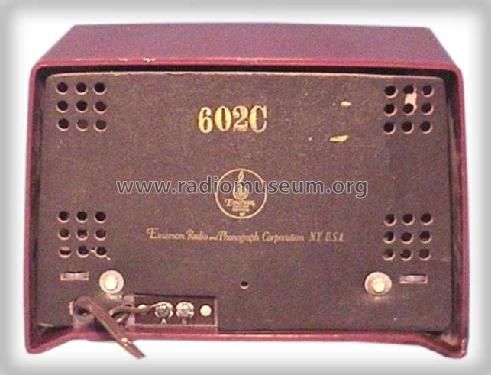
602C Conquerer Ch= 120102A
Emerson Radio & Phonograph Corp.; New York, NY
- Country
- United States of America (USA)
- Manufacturer / Brand
- Emerson Radio & Phonograph Corp.; New York, NY
- Year
- 1949/1950
- Category
- Broadcast Receiver - or past WW2 Tuner
- Radiomuseum.org ID
- 38637
-
- alternative name: Emerson Television
EBay Nr. 320052528104 Bild bearbeitet.
Ebay Nr. 320052528104 Bild bearbeitet.
Ebay Nr. 320052528104 Bild bearbeitet.
Click on the schematic thumbnail to request the schematic as a free document.
- Number of Tubes
- 7
- Main principle
- Superhet with RF-stage; ZF/IF 10700 kHz; 2 AF stage(s)
- Tuned circuits
- 8 FM circuit(s)
- Wave bands
- FM Broadcast Band Only
- Power type and voltage
- AC/DC-set / 105-125 Volt
- Loudspeaker
- Permanent Magnet Dynamic (PDyn) Loudspeaker (moving coil)
- Material
- Plastics (no bakelite or catalin)
- from Radiomuseum.org
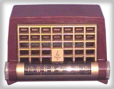
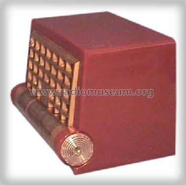
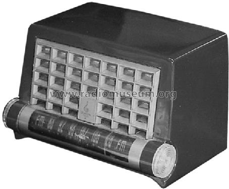
- Model: 602C Conquerer Ch= 120102A - Emerson Radio & Phonograph
- Shape
- Tablemodel without push buttons, Mantel/Midget/Compact up to 14
- Dimensions (WHD)
- 9 x 6.25 x 5.5 inch / 229 x 159 x 140 mm
- Notes
-
FM (88-108MHz) band. Color is Maroon.
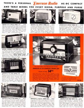
- Price in first year of sale
- 29.95 $
- External source of data
- Ernst Erb
- Source of data
- Guide to Old Radios
- Circuit diagram reference
- Rider's Perpetual, Volume 23 (last), covering up to 1954
- Mentioned in
- Machine Age to Jet Age II
- Literature/Schematics (1)
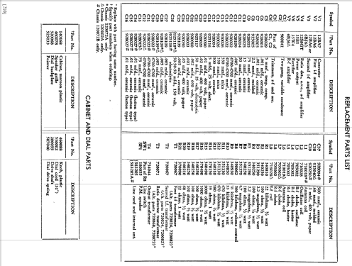
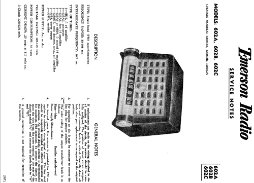
- Emerson Radio and Television Service Manual (Page 207)
- Literature/Schematics (3)
- Emerson Folder Form. No. 50-628 for "New 1950".
- Other Models
-
Here you find 2101 models, 1158 with images and 1659 with schematics for wireless sets etc. In French: TSF for Télégraphie sans fil.
All listed radios etc. from Emerson Radio & Phonograph Corp.; New York, NY
Forum contributions about this model: Emerson Radio &: 602C Conquerer Ch= 120102A
Threads: 1 | Posts: 1
Fellow Radiophiles,
The topic of mixing modes at the front ends of superheterodyne radios has come up several times. Most recently, by Prof Rudolph in a thread explaining the operation of a pentode frequency converter with additive mixing at the cathode (I read this German language thread with an on-line translator). This topology was use in some 1930's radios, and became nearly universal in transistor radio designs in the 1950's, until IC's offered greater versatility in mixer design without increasing cost.
The two fundamental mixing modes are additive and multiplicative. Additive mixing is accomplished by adding the RF and Local Oscillator (LO) signals before applying them to a non-linear element. The large amplitude of the LO signal forces operation of the mixing tube or transistor as non-linear mixing elements. Multiplicative mixing is accomplished when the RF and LO signals are applied to different terminals of the mixing element, with respect to a common terminal, like perhaps, the cathode.
Additive mixing tends to yield a lower conversion gain, while multiplicative mixing with pentodes or heptodes tends to produce more noise. The maximum range for FM reception is limited by noise generated in tubes or transistors, and resistors or lossy elements in the radio front end. This led eventually to a general adoption of additive mixing in FM front end design. 1940's FM radios usually used mulitiplicative mixing, while by the 1960's additive mixing was used exclusively.
Multiplicative and Additive mixing used simultaneously
The Emerson 602A, 602B and 602C FM receivers from 1950 use the high gain 12BA7 pentagrid frequency converter, which was designed for multiplicative mixing. The 12BA7 is rated to yield 950uS of conversion tansconductance in the AM band. This is the highest conversion gain among common American pentagrid converters. Compare to the ubiquitous 12BE6 with gmc=475uS, or the older 12SA7 with gmc=450uS.
The increased transconductance of the 12BA7 is helpful to increase gain, and may also help reduce intrinsic tube noise.
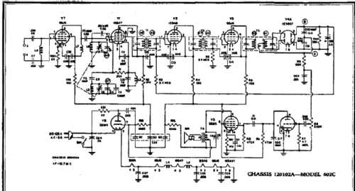
The following front end schematic is for the Emerson 602C, which includes the 6BJ6 RF preamp front end that was designed for reduced partition noise that is inherent to tubes with multiple grids, as the cathode current splits between the positively biased screen grid G2 and the plate.
The unusual aspect of the 12BA7 frequency converter circuit is the addition of C38=2.2pF to assist in the internal multiplicative mixing process with an additive component. Some of the local oscillator signal from the local oscillator control grid G1 is added to the RF input grid G3. This capacitor is usually present only in additive mixing circuits using triodes or transistors.

The following schematic is for the 602B version, which does not include the 6BJ6 RF preamp. The additive mixing capacitor is C8=2.2pF, and is seen more clearly in this schematic. The reactance of 2.2pF at 100MHz is only 723Ω.

While the inclusion of additive mixing will not eliminate the partition noise inherent in this heptode, it probably increases transconductance gain in the FM band, which helps reduce noise.
Regards,
-Joe
Joe Sousa, 30.Jan.11