- Land
- Grossbritannien (UK)
- Hersteller / Marke
- Fidelity Radio Co. Ltd.; London
- Jahr
- 1973 ?
- Kategorie
- Rundfunkempfänger (Radio - oder Tuner nach WW2)
- Radiomuseum.org ID
- 203991


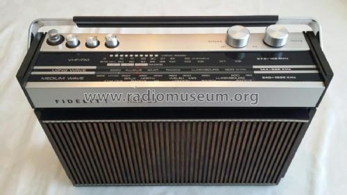

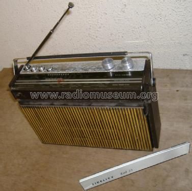
Trim missing above speaker grill
Klicken Sie auf den Schaltplanausschnitt, um diesen kostenlos als Dokument anzufordern.
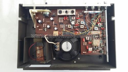
- Anzahl Transistoren
- 11
- Hauptprinzip
- Superhet allgemein; ZF/IF 470 / 10700 kHz; 4 NF-Stufe(n); kein Zusatz
- Anzahl Kreise
- 5 Kreis(e) AM 6 Kreis(e) FM
- Wellenbereiche
- Langwelle, Mittelwelle und UKW (FM).
- Betriebsart / Volt
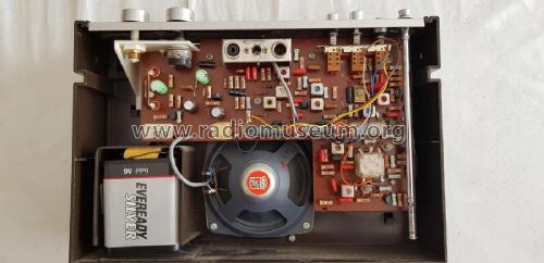
- Batterien / Niedervolt Stromversorgung (power jack) / 9 Volt
- Lautsprecher
- Dynamischer LS, keine Erregerspule (permanentdynamisch) / Ø 10 cm = 3.9 inch
- Belastbarkeit / Leistung
- 0.5 W (Qualität unbekannt)
- Material
- Plastikgehäuse (nicht Bakelit), Thermoplast
- von Radiomuseum.org
- Modell: RAD23 - Fidelity Radio Co. Ltd.;
- Form
- Reisegerät > 20 cm (netzunabhängig betreibbar)
- Abmessungen (BHT)
- 300 x 200 x 80 mm / 11.8 x 7.9 x 3.1 inch
- Bemerkung
-
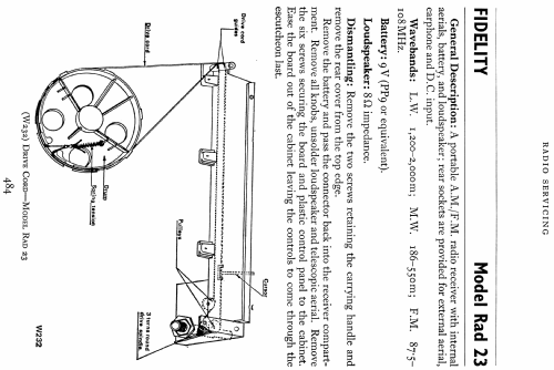
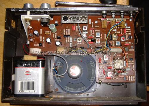
Rear: Earphone/tape out, DC 9V in and Socket for car aerial. Though Silicon transistor -Ve ground, the outer of the external 9V DC jack socket is +Ve 9V PP9 battery last seen in local shops 2010. Still available online 2011. Rear cover held on by side carry handle screws. All "lockfit" Silicon except Audio Out is Germanium AC129 driver and AC127 + AC128 complementary output
The unlisted transistor is used as a bias diode (D4), for the AC127 & AC128 output stage.
- LW 1200 - 2000m
- MW 186 - 550m
- FM/VHF/UKW 87.5 - 108 MHz
PP9 battery pack.
Sockets for car aerial, earphone/external speaker and 9V DC in (outer positive)
- Nettogewicht
- 1.880 kg / 4 lb 2.3 oz (4.141 lb)
- Datenherkunft
- Radio And Television Servicing books (R&TVS)
- Schaltungsnachweis
- Radio and TV Servicing books (R&TVS) book
- Literaturnachweis
- R&TVS 1974, page 484
- Autor
- Modellseite von Michael Watterson angelegt. Siehe bei "Änderungsvorschlag" für weitere Mitarbeit.
- Weitere Modelle
-
Hier finden Sie 74 Modelle, davon 60 mit Bildern und 39 mit Schaltbildern.
Alle gelisteten Radios usw. von Fidelity Radio Co. Ltd.; London
Sammlungen
Das Modell RAD23 befindet sich in den Sammlungen folgender Mitglieder.