10T1 "Locomotive"
General Electric Co. (GE); Bridgeport CT, Syracuse NY
- País
- Estados Unidos
- Fabricante / Marca
- General Electric Co. (GE); Bridgeport CT, Syracuse NY
- Año
- 1949/1950
- Categoría
- Televisión (TV) o monitor
- Radiomuseum.org ID
- 170094
-
- Brand: Musaphonic


Haga clic en la miniatura esquemática para solicitarlo como documento gratuito.
- Numero de valvulas
- 20
- Válvulas
- 6AU6 6AG5 12AT7 6AG5 6AG5 6AG5 12AT7 10BP4 6SL7GT 6AL5 12SN7GT 12SN7GT 19BG6G 1B3GT 25W4GT 6AU6 6AU6 6AL5 6SQ7 25L6GT
- Principio principal
- Superheterodino con paso previo de RF; ZF/IF 45750/4500 kHz
- Gama de ondas
- Bandas de recepción puestas en notas.
- Tensión de funcionamiento
- Red: Corriente alterna (CA, Inglés = AC) / 115 Volt
- Altavoz
- Altavoz dinámico (de imán permanente) / Ø 4 inch = 10.2 cm
- Potencia de salida
- 1 W (unknown quality)
- Material
- Bakelita
- de Radiomuseum.org
- Modelo: 10T1 "Locomotive" - General Electric Co. GE;
- Forma
- Sobremesa de cualquier forma, detalles no conocidos.
- Ancho, altura, profundidad
- 11.8 x 14.7 x 20.3 inch / 300 x 373 x 516 mm
- Anotaciones
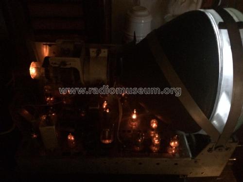
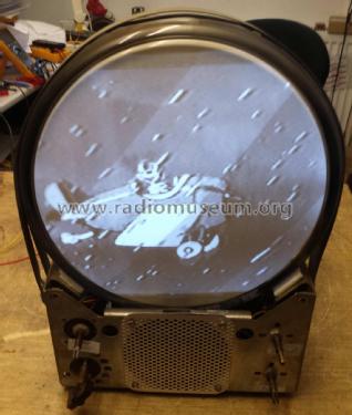
- In 1949-50, General Electric produced multiple models of 10-inch TVs with an upright bakelite cabinet with a streamlined appearance. These models are very popular with antique TV collectors today and have have been given the nickname "Locomotive" because of their unique shape (and possibly because GE also produces actual train locomotives). All sets in this series have 12-channel VHF tuners and use intercarrier sound. Some early models have electromagnet-type speakers; later models have PM speakers.
The earliest models in the series are the 800A, 800B, and 805 early version (with no letter chassis marking). Rider states that the difference between the 800A and 800B relates to the lengths of the front panel control shafts. All models in this grouping have a rectangular CRT mask. Electrically, all three models appear to be identical, with 19 tubes (including 25Z6GT damper tube, unique to these models), and a full-wave voltage doubler which provides a "split" or "stacked" B+ arrangement. These early models have a focus coil that can be adjusted to slide forward or backwards, but not twist; picture centering is accomplished with a separate centering ring on the neck of the CRT. The difference between the 800 and 805 models is not clear, nor is the chronological order of production of these three models clear.
Based on examination of the circuitry shown in Rider, it can be concluded that the next grouping of models produced includes the 800C, 800D, and the middle versions of the 805 (with S or T chassis). Like the first grouping, these models have rectangular CRT mask. These models have 19 tubes including a 25W4GT damper, and a half-wave voltage doubler is used in a slightly modified stacked B+ arrangement. There are minor differences visible on the schematics between the 800 and 805 models in this grouping, and Rider notes a control shaft length diffrence between 800C and 800D. Additional degrees of freedom are provided for the adjustment of the focus coil, allowing the centering to be adjusted by sliding/rotation of the focus coil, and eliminating the need for a separate centering ring. The chronological ordering of models within this grouping is not clear.
Next came the late versions of the 805 (with U and W chassis). In this model, GE added an additional tube (20 tubes total) for an improved horizontal synchronization circuit. A 6AL5 dual diode was used for the horizontal discriminator, and a 12SN7GT used in the sync separator circuitry was replaced with a 6SL7GT (thus allowing the series filamant strings to have minimal change from previous models). Another change is the use of a 6AG5 tube in place of a 6AU6 in the tuner second RF stage. Although Rider and most advertising literature shows rectangular CRT mask for all 805 models, there is some possibility that some of the late 805s had a double-D mask.
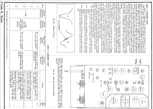
The 805 was replaced by the 10T1, in which another tube was added (2nd 6AU6 sound IF) and one was removed (6AL5 video det / DC restorer replaced by germanium diodes). In the video IF stages, type 6AG5 replaced the earlier 6AU6 tubes. According to Rider, starting in January 1950, these 6AG5s in the video IF, and the 6AG5 in the tuner second RF stage were all replaced with 6BC5. This establishes a date of January 1950 for some point during the 10T1 model run. The 10T1 has a double-D CRT mask.
The last model in the series is the 10T6, which includes all of the changes noted above, and uses a 10FP4A CRT with aluminized screen in place of the earlier 10BP4 for brighter picture and elimination of the need for an ion trap. Since January 1950 occured during 10T1 production, it is assumed that the 10T6 is a 1950 model.
Collectors should note that due to fragility of the bakelite cabinet, it is wise to ship the chassis, CRT, and cabinet separately. These models were originally shipped by GE with CRT not installed.
- Precio durante el primer año
- 189.00 $
- Procedencia de los datos
- -- Original prospect or advert
- Referencia esquema
- Photofact Folder, Howard W. SAMS
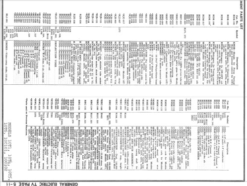
- Documentación / Esquemas (1)
- Rider TV 5-1; SAMS set 96 folder 4
- Autor
- Modelo creado por Thomas Albrecht. Ver en "Modificar Ficha" los participantes posteriores.
- Otros modelos
-
Donde encontrará 2952 modelos, 2166 con imágenes y 2069 con esquemas.
Ir al listado general de General Electric Co. (GE); Bridgeport CT, Syracuse NY
Colecciones
El modelo 10T1 es parte de las colecciones de los siguientes miembros.
Contribuciones en el Foro acerca de este modelo: General Electric Co.: 10T1 "Locomotive"
Hilos: 1 | Mensajes: 1
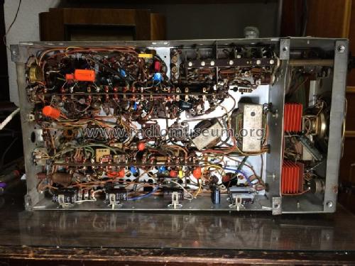
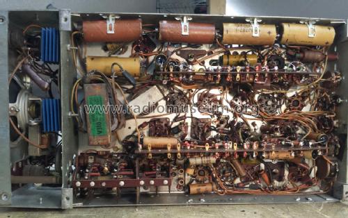
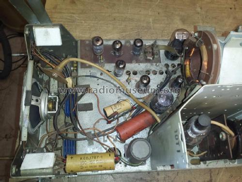
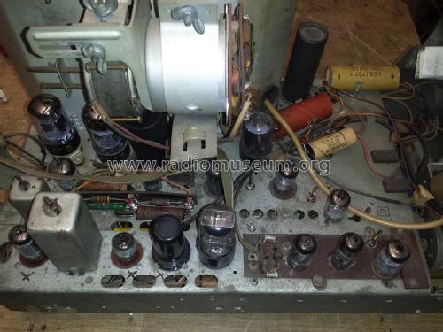
These GE Locomotives are popular TVs for collectors, and restoration threads come up often. I just finished a 10T1 (similar to the 805 and other Locomotives), and thought I'd pass along some of the fixes, since these seem to have a pattern to them, with most of these sets needing some of the same things. In addition to the usual replacement of paper and electrolytic capacitors, replacement of bad tubes, and cleaning of tuner and potentiometer contacts, the following problems were corrected in this set:
1. Open filament choke. Just one bad one in this set, but sometimes you'll see multiple failures, due to corrosion with age. The inductors in question are L371-L375 in Rider, or L51-L55 in Sams. Replace with any low resistance (less than 3 ohms) ferrite inductor (the ones that look like a 1 watt resistor with a single layer coil around them of about #24 wire). These are easily scavanged from junker sets.
2. Burned up filament string series dropping resistors, along with their terminal strips inside the HV cage. Replaced with modern 10 watt 75 ohm power resistors and some new terminal strips. The resistors are R373 and R374 in Rider, R116 and R117 in Sams.
3. Open 1700 ohm power resistor in focus circuit. This is located on the little vertical circuit board on the top center of the chassis under the picture tube neck. It's R377 in Rider, R111 in Sams. Replace with modern 1700 ohm 5 watt resistor. Alternatively, a 2000 ohm 5 watt resistor with a 12K ohm 1 watt resistor in parallel.
4. Replace the selenium rectifiers with 1N4007 diodes. To bring the B+ back to the correct value, remove the 4.6 ohm power resistor (R115 in Sams, R372 in Rider) and replace it with a 20 ohm 10 watt power resistor (or two 10 ohm 5 watt power resistors in series, as I did this time).
5. Replace the "large" micas in the horizontal AFC to improve sync stability. I replaced them with 630 V polystyrene caps, but 500 V micas will also work. These are the following:
3900 pF: C96 and C102 in Sams, C398 and C404 in Rider
1800 pF: C99 in Sams, C402 in Rider
1000 pF: C101 in Sams, C403 in Rider
If the sync is still behaving badly, check all resistor values in the sync separator and horizontal AFC stages, and also replace remaining small value micas in these circuits.
6. Speaker replaced. It's kind of funny, but for some reason, the location of the speaker on these GE chassis is right where the serviceman is tempted to grab the chassis. I've damaged a few speakers myself on a few of these chassis, and I also notice that the speakers already tend to be damaged by previous servicemen in the past. This set had a totally destroyed speaker when it came to me.
7. This set has the "faint white line" problem when using with certain signal sources (such as the Digital Stream DTV converter box). This was discussed in great depth in this Philco Predicta thread on ARF. The net is that increasing the value of a capacitor in the filter network right after the video detector can improve this a lot. In the GE 10T1, the capacitor is a 5 pF capacitor inside the video detector can (L36 in Sams, L247/248 in Rider, with the capacitor itself labeled C266 in Rider). To fix the problem, you add an additional 47 pF in parallel with this capacitor. Fortunately you can do this on one of the external terminals of the video detector can; you don't need to go inside it. Look for the terminal with L37 (Sams) or L249 (Rider) connected to it, and add a 47 pF cap to chassis ground (right next to the can; don't use the negative common bus). Choosing the value is a matter of taste. With about 30 pF, the sharpness of the picture is hardly affected at all, but the faint white line still shows up a bit. At 60 pF, the faint white line is completely gone, but picture sharpness is noticeably affected. 47 pF looked like a good compromise on this set, although sometimes I choose lower, since I like a very sharp picture.
8. Although I often replace the old germanium diodes (this GE has one as the video detector, and another one in the DC restoration circuit), the ones in this set seem to be holding up nicely. Will keep an eye on it for a while. Not a bad idea to replace them if you have video image quality problems, or want to prevent a future failure.
Thomas Albrecht, 09.Apr.12