Dynamotor 5DY83AB1 Western Electric Dynamotor DM-33-A
General Electric Co. (GE); Bridgeport CT, Syracuse NY
- País
- Estados Unidos
- Fabricante / Marca
- General Electric Co. (GE); Bridgeport CT, Syracuse NY
- Año
- 1940–1945
- Categoría
- Equipo Militar (sin Re, Tr y TRX)
- Radiomuseum.org ID
- 218687
-
- Brand: Musaphonic


- Gama de ondas
- - no hay
- Altavoz
- - - No hay salida de sonido.
- de Radiomuseum.org
- Modelo: Dynamotor 5DY83AB1 Western Electric Dynamotor DM-33-A - General Electric Co. GE;
- Ancho, altura, profundidad
- 7.9 x 3.9 x 3.5 inch / 201 x 99 x 89 mm
- Anotaciones
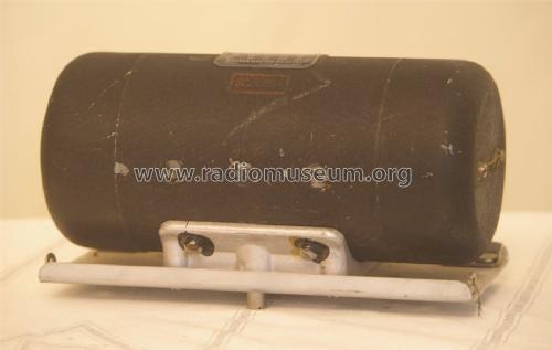
- Dynamotor, WW2 Vintage 1940 – 1945 used in aircraft radios:
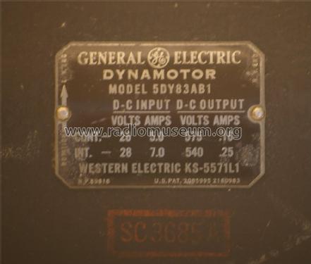
Model Plate on the Dynamotor case:
General Electric, Dynamotor,
Model 5DY83AB1.
D-C Input: Volts - Continuos 28 V, Amps 5.0; Intermittent 28 V, Amps 7.0
D-C Output: Volts - Continuos 575 V, Amps 0.16; Intermittent 540 V, Amps 0.25
Western Electric KS-5571L1
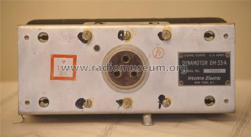
Model Plate on Signal Corps Frame:
Signal Corps U.S. Army
Dynamotor DM-33-A
Western Electric, New York N.Y.
- Peso neto
- 11.75 lb (11 lb 12 oz) / 5.335 kg
- Autor
- Modelo creado por Bruce Morgenstern. Ver en "Modificar Ficha" los participantes posteriores.
- Otros modelos
-
Donde encontrará 2962 modelos, 2174 con imágenes y 2074 con esquemas.
Ir al listado general de General Electric Co. (GE); Bridgeport CT, Syracuse NY
Colecciones
El modelo Dynamotor 5DY83AB1 es parte de las colecciones de los siguientes miembros.
Contribuciones en el Foro acerca de este modelo: General Electric Co.: Dynamotor 5DY83AB1 Western Electric Dynamotor DM-33-A
Hilos: 1 | Mensajes: 1
COMMAND SETS, SCR-274N & DYNAMOTOR DM-33:
This series of radios are basically the same as the Navy radios in the ARA and ATA range. They were adopted by the Signal Corps and were their main aircraft communication radio for most of World War 2. The N suffix to the SCR-274N signifies a Navy design. They were used in many different bomber and fighter aircraft types for communication between aircraft. A fighter like the P-38 Lightning, and P-51 Mustang would usually have 1 receiver and 1 transmitter fitted. A bomber like the B-17 Flying Fortress, the B-24 Liberator, and the B-29 Super Fortress would often have 3 receivers and 3 transmitters fitted. These radios were available in black and unpainted finish.
There are four receivers: the BC-453 (0.19-0.55 mcs), BC-946 (0.52-1.5 mcs), BC-454 (3-6 mcs), and the BC-455 (6-9.1 mcs). The receivers were remotely mounted and controlled, with a BC-473 one receiver control box, a BC-496 two receiver control box, or a BC-450 three receiver control box. Each receiver had its own dynamotor. The receivers were mounted in racks, with several bays, the FT-233 held one receiver, the FT-227 held two receivers, the FT-220 held three receivers, and the FT-264 held four receivers. When the receivers were remotely controlled, a plug in on the front, called an adapter was used to enable the remote control. This adapter, the FT-230, was merely a link inside the box. When the receiver was used in local control, the adapter FT-260 had a volume control and ON/OFF/BFO switch. An MC-237 local tuning knob was used for local tuning. An FT-310 adapter was available that had a connector on the front so that power was available for other equipment. The BC-946 usually had this type of adapter.
There are four transmitters: BC-696 (3-4 mcs), BC-457 (4-5.3 mcs), BC-458 (5.3-7 mcs), and the BC-459 (7-9.1 mcs). The transmitters were similarly remotely mounted and controlled, with the BC-451 control box, which controlled from 1 to 4 transmitters. The transmitters were mounted in racks, with several bays, the FT-234 held one transmitter, the FT-226 held two transmitters, the FT-276 held three transmitters, and the FT-331 held four transmitters. There was a BC-442 antenna changeover relay box, that also had a RF antenna current meter. The power for the transmitters came from the BC-456modulator which also has a DM-33 dynamotor to generate the high voltage. The handheld microphone used was a T-17.
BC-453
Frequency coverage: 190-550 kcs Intermediate Frequency: 85 kcs Valves: 12SK7 (VT131) RF amp, 12K8 (VT132) mixer, 12SK7 (VT131) first IF amp, 12SK7 (VT131) second IF amp, 12SR7 (VT133) detector and CW oscillator, 12A6 (VT134) audio output. This example was made by Western Electric serial number 68444.

DM-33 TRANSMITTER DYNAMOTOR
The transmitters use one dynamotor for their High Tension supply. It is continuously rated at 575 volts dc at 160 ma. They only need one, as only one transmitter is on at a time. The dynamotor is located on the BC-456 modulator.

BRIEF HISTORY
The Type K command sets were conceived in 1934 by Dr. Frederick H. Drake, chief designer of the Aircraft Radio Corporation. At this time, the Army Air Corps was using the SCR-183 and the Navy the very similar GF/RU short range TRF radios. In 1937, Dr. Atherton Noyes from General Radio was employed to design the transmitters. Five years were spent, designing, testing, and improving the radios. In 1939 the Navy tested the prototype, and immediately bought production models. They were the RAT (13.5-20 mcs and 20-27 mcs receivers) followed by RAV (190 kc to 27 mc). The Army, after suffering failure of its new crystal controlled SCR-240 design, ordered them in June 1940 as the SCR-274N (N meaning Navy). The Aircraft Radio Corporation then began making the ARA/ATA design as well as the SCR-274N. Other companies like Western Electric and Colonial Radio also made them. In 1942-43 an improved version called the AN/ARC-5 was introduced for the Navy. The VHF designs began to appear late in the war and had extensive civilian use after 1945. The design was eventually extended to become the civilian A.R.C. Type 12 and the military adopted a subset of these radios as the AN/ARC-60 VHF sets used in the Korean war and up until about 1960.
Article submitted by: Bruce Morgenstern, with permission from copyright holder, Ray Robinson.
Copyright: Ray Robinson vk2ilv
(updated 17 August 2005)
Reference:
R. E. E. ROBINSON
Speech Hearing and Language Research Centre
Macquarie University
North Ryde 2109
Bruce Morgenstern, 14.Jan.14