- Land
- Frankreich / France
- Jahr
- 1928
- Kategorie
- Rundfunkempfänger (Radio - oder Tuner nach WW2)
- Radiomuseum.org ID
- 70835


Dépliant Grillet


From auction site Ebay.
Dépliant Grillet
From auction site Ebay.
From auction site Ebay.

From auction site Ebay.
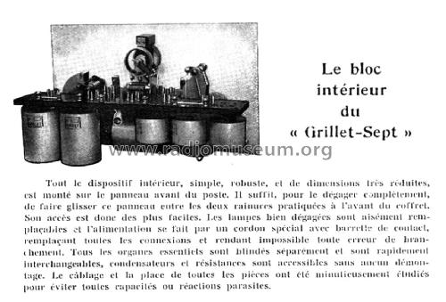
Première page d'un dépliant GRILLET
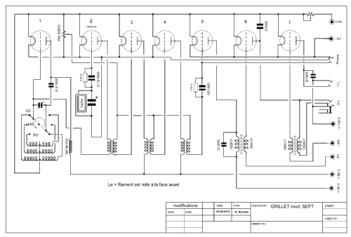
Klicken Sie auf den Schaltplanausschnitt, um diesen kostenlos als Dokument anzufordern.
- Anzahl Röhren
- 7
- Hauptprinzip
- Superhet allgemein
- Wellenbereiche
- Langwelle, Mittelwelle (LW+MW).
- Betriebsart / Volt
- Akku und/oder Batterie / 4 & 40 & 80 & 120 Volt
- Lautsprecher
- - Dieses Modell benötigt externe(n) Lautsprecher.
- Material
- Gerät mit Holzgehäuse
- von Radiomuseum.org
- Modell: Grillet-Sept - Grillet, F., J. Béné voir
- Form
- Tischgerät, Truhenform, meist mit Deckel (NICHT Schrägpult).
- Abmessungen (BHT)
- 420 x 215 x 210 mm / 16.5 x 8.5 x 8.3 inch
- Bemerkung
-
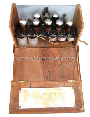
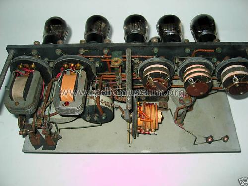
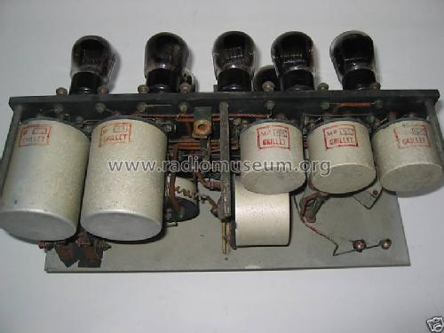
Poste à 7 lampes intérieures, fonctionnant sur cadre. Superhétérodyne à système Ultradyne (voir text en anglais), détection grid-leak.
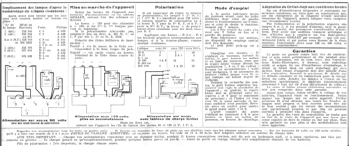
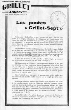
Les étages finales BF peuvent aussi être employés à tension réduite de 80 au lieu de 120 volts. Une batterie "C" pour la polarisation des deux lampes finales BF est toujours nécessaire. La tension dépend de la tension appliquée aux anodes et de les lampes utilisées. Exemple de batterie.
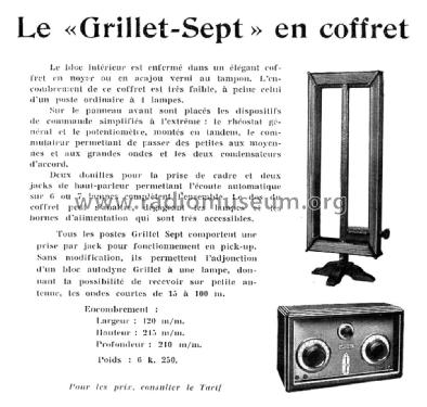
Deux prises HP pour l'audition automatique sur 6 ou 7 lampes (jeux des lampes alternatives voir documentation). Prise pick-up.
Possibilité d'adjonction d'un Bloc Autodyne pour la réception des OC de 15 a 100 m, sans modification, sur petite antenne.
Coffret en noyer ou acajou verni au tampon.
Voir aussi modèles Grillet-Sept No. 7 en coffret traditionel et Grillet-Sept version luxe.
Ultradyne principle. The Ultradyne circuit was invented by Robert E. Lacault and was first marketed by the Phenix Radio Corporation in February 1924.
Excerpt from an internet source:
"The Ultradyne was touted to be an improvement over the standard 1920s superheterodyne circuit. Instead of injecting the oscillator signal into the grid circuit of the first detector, as was the standard practice at the time, the Ultradyne principle used the oscillator to modulate the plate of the first detector. The modulation method is somewhat unusual and some people assume there is a wiring error at a first glance of the schematic diagram. The plate of the first detector did not obtain its voltage directly from the B+ supply; it obtains its voltage from the grid of the oscillator tube (through the primary of the first IF transformer)."
- Nettogewicht
- 6.250 kg / 13 lb 12.3 oz (13.767 lb)
- Originalpreis
- 1,500.00 FRF
- Literaturnachweis
- Radios von gestern, 2. Auflage
- Literatur/Schema (1)
- - - Manufacturers Literature
- Literatur/Schema (3)
- Le Journal de Fourmies, 01.12.1928
- Literatur/Schema (4)
- -- Original prospect or advert (Dépliant Grillet)
- Weitere Modelle
-
Hier finden Sie 27 Modelle, davon 22 mit Bildern und 5 mit Schaltbildern.
Alle gelisteten Radios usw. von Grillet, F., J. Béné (voir aussi Radio-Annécia), Zuccolo-Rochet et Cie.; Annecy
Sammlungen
Das Modell Grillet-Sept befindet sich in den Sammlungen folgender Mitglieder.