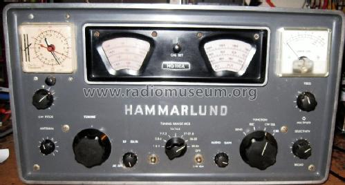
HQ-110A metal plate between scales
Hammarlund Mfg. Co. Inc.; New York, NY
- Country
- United States of America (USA)
- Manufacturer / Brand
- Hammarlund Mfg. Co. Inc.; New York, NY
- Year
- 1958–1969
- Category
- Amateur-Receiver (amateur bands, may include broadcast bands)
- Radiomuseum.org ID
- 196541


- Number of Tubes
- 11
- Main principle
- Superhet with RF-stage; 2 AF stage(s)
- Wave bands
- Wave Bands given in the notes.
- Power type and voltage
- Alternating Current supply (AC) / 115 Volt
- Loudspeaker
- - This model requires external speaker(s).
- Power out
- 1 W (unknown quality)
- Material
- Metal case
- from Radiomuseum.org
- Model: HQ-110A [metal plate between scales] - Hammarlund Mfg. Co. Inc.; New
- Shape
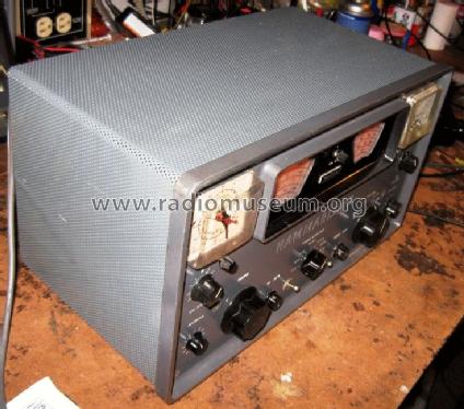
- Tablemodel, low profile (big size).
- Dimensions (WHD)
- 418 x 231 x 232 mm / 16.5 x 9.1 x 9.1 inch
- Notes
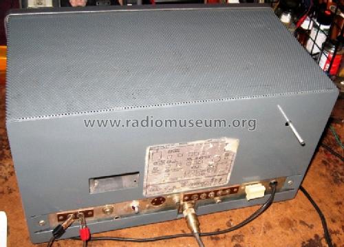
- The Hammarlund model HQ-110A is a HAM bands receiver for 6, 10, 15, 20, 40, 80 and 160 Meters. Optional 2 meters VHF converter and "Telechron Auto-Timer" clock. There are at least two variants: This one here with a small metal tag that says HQ 110a between the two scales and one which has s metal tag on the front with "VHF" and below a silkscreen with "HAMMARLUND HQ 110 A". This model has a pre-amp on 2 & 6 meters. We believe it is the last of the series.
Production Changes (by Bill Henry, Deland, FL, USA):
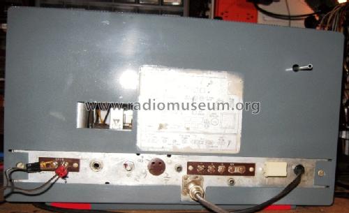
The HQ-110 was produced in at least 3 serial number ranges. The first run includes serial numbers up to 4199; the second run includes serial numbers from 5000 to 7000; and the final run includes serial numbers above 7000. The serial number can be found stamped into the rear apron of the chassis.
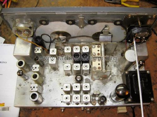
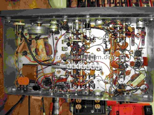
The major changes in the second serial run are in the area of V1 and V2 and in the BFO circuit. The coupling arrangement between T1 and T2 was modified significantly, as were parts of the second mixer circuit. The second mixer crystal was changed from a 3.49 Mc to 2.58 Mc. Also, there were finally some further attempts at temperature compensation to help to reduce the inherent drift of the receiver. In addition, the BFO circuit was changed considerably so that its output comes from the plate rather than from the cathode as previously done.
In the third serial run, there were further changes in the T1/T2 coupling as well as new changes in the RF stage and the second mixer. Most notably, the Antenna coils are no longer gang-tuned to the mixer and local oscillator. The antenna coils are now resonated by the antenna trimmer only, leaving the main tuning capacitor a 2-section variable, rather than a 3-section as it was previously. According to a Product Addendum covering the second and third runs, 6 capacitors were added to improve stability in the high frequency oscillator and BFO sections; 2 coils were added to the second mixer and local oscillator to improve stability; and a resistor across the output transformer was added to provide an emergency speaker load.
- Net weight (2.2 lb = 1 kg)
- 11.4 kg / 25 lb 1.8 oz (25.11 lb)
- Price in first year of sale
- 299.00 $
- Mentioned in
- Shortwave Receivers - Past & Present (3rd ed.)
- Literature/Schematics (1)
- Communications Receivers
- Author
- Model page created by Konrad Birkner † 12.08.2014. See "Data change" for further contributors.
- Other Models
-
Here you find 144 models, 92 with images and 58 with schematics for wireless sets etc. In French: TSF for Télégraphie sans fil.
All listed radios etc. from Hammarlund Mfg. Co. Inc.; New York, NY
Collections
The model HQ-110A is part of the collections of the following members.