Condenser Checker C-1
Heathkit (Brand), Heath Co.; Benton Harbor (MI)
- Country
- United States of America (USA)
- Manufacturer / Brand
- Heathkit (Brand), Heath Co.; Benton Harbor (MI)
- Year
- 1948 ?
- Category
- Service- or Lab Equipment
- Radiomuseum.org ID
- 80758
-
- alternative name: Heath Company

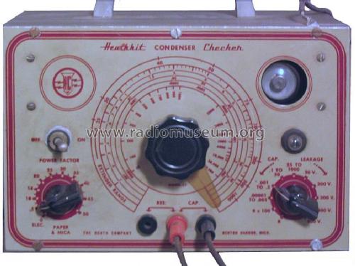
Ebay Nr. 170102025544 Bild bearbeitet.
Ebay Nr. 170102025544 Bild bearbeitet.
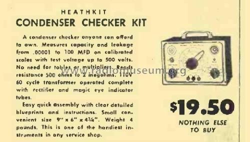
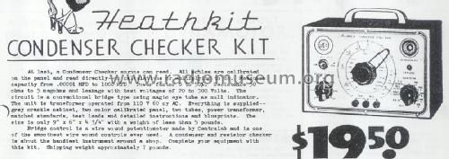
Heathkit C-1 ad in RadioNews May 1948 p102
Heathkit C-1 in June 1948 ad
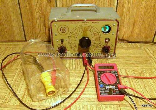
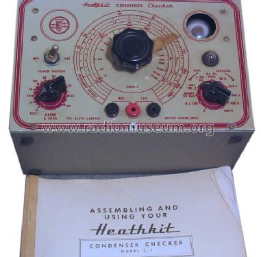
Heathkit C-1 in actual use
Click on the schematic thumbnail to request the schematic as a free document.
- Number of Tubes
- 2
- Power type and voltage
- Alternating Current supply (AC) / 105-125 Volt
- from Radiomuseum.org
- Model: Condenser Checker C-1 - Heathkit Brand, Heath Co.;
- Shape
- Tablemodel, with any shape - general.
- Notes
-
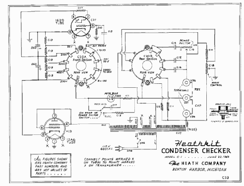
The is a modified version of the original schematic is for the Heathkit C-1 Condenser Checker, the modification replaced part numbers with actual component values. Please note that the network of 30k ohm resistors should drop voltages equally. The 20 VDC switch setting should per the schematic produce an actual voltage of 100 VDC. However, the actual voltage on a capacitor under test would be reduced by the voltage required by the neon lamp.
- Net weight (2.2 lb = 1 kg)
- 4 lb (4 lb 0 oz) / 1.816 kg
- Price in first year of sale
- 19.50 US$
- Source of data
- Radio News
- Mentioned in
- -- Schematic (Heathkit ads)
- Literature/Schematics (1)
- Chuck Penson: "Heathkit Test Equipment Products", page 2-01
- Author
- Model page created by Bernd Pötzsch. See "Data change" for further contributors.
- Other Models
-
Here you find 720 models, 703 with images and 507 with schematics for wireless sets etc. In French: TSF for Télégraphie sans fil.
All listed radios etc. from Heathkit (Brand), Heath Co.; Benton Harbor (MI)
Collections
The model Condenser Checker is part of the collections of the following members.
Forum contributions about this model: Heathkit Brand,: Condenser Checker C-1
Threads: 1 | Posts: 1
An electrolytic can be reformed in step-wise fashion. The neon bulb (below the eye tube) lights when the reforming current is about 2 mA or more. The reforming process starts with the voltage step switch set at the lowest voltage at which the neon bulb lights. As reforming progresses, the neon bulb will go out when reforming current drops below 2 mA. At that point the next higher voltage step can be selected until the capacitor shows full proper voltage on an external voltmeter. When the reforming process is complete, the tester's power is switched off and the step switch moved to the "R" position to quickly bring the voltage across the capacitor back to zero. The "R" setting places a 1000 ohm resistor across the test leads.
Rich Post, 31.Jan.22